Once you are familiar with the Text and its options, the next thing would naturally be Dimension. This is the most significant as well as intricate portion of AutoCAD for more than one reason –
1. Without Dimension the entire drawing and the geometry therein is useless.
2. Dimensions are needed to make any drawing usable as a Working Drawing.
3. If there are the most variables and settings for any AutoCAD command, it’s Dimension.
4. A single small mistake or negligence in mistake in Dimension can cost you a fortune.
5. Dimensions are the integral and phenomenal part of any Drawing Analysis.
Phew…! Are you scared of Dimensions, now? Don’t be. Whatever written above are just the facts and those need to be thoroughly understood and rightly implemented not anxiously dreaded…!?!
Alright, now today just take a look at the Overview of Dimension to start with. As for all other major elements of AutoCAD, Dimensions also do have settings called as Dimension Style.
1. Without Dimension the entire drawing and the geometry therein is useless.
2. Dimensions are needed to make any drawing usable as a Working Drawing.
3. If there are the most variables and settings for any AutoCAD command, it’s Dimension.
4. A single small mistake or negligence in mistake in Dimension can cost you a fortune.
5. Dimensions are the integral and phenomenal part of any Drawing Analysis.
Phew…! Are you scared of Dimensions, now? Don’t be. Whatever written above are just the facts and those need to be thoroughly understood and rightly implemented not anxiously dreaded…!?!
Alright, now today just take a look at the Overview of Dimension to start with. As for all other major elements of AutoCAD, Dimensions also do have settings called as Dimension Style.
 A dimension style is a named collection of dimension settings that controls the appearance of dimensions, such as arrowhead style, text location, and lateral tolerances. You create dimension styles to specify the format of dimensions quickly, and to ensure that dimensions conform to industry or project standards.
- When you create a dimension, it uses the settings of the current dimension style
- If you change a setting in a dimension style, all dimensions in a drawing that use the style update automatically
- You can create dimension sub-styles that, for specified types of dimensions, deviate from the current dimension style
- If necessary, you can override a dimension style temporarily
You can control the appearance of dimensions by changing settings. For convenience and to help maintain dimensioning standards, you can store these settings in dimension styles.
- Compare Dimension Styles and Variables
You can view all the settings in a dimension style. Dimension styles used in externally referenced drawings are differentiated from those defined in your current drawing. - Control Dimension Geometry
You can control the appearance of dimension lines, extension lines, arrowheads, and center marks. - Control Dimension Text
You can control the placement of dimension text, arrowheads, and leader lines relative to the dimension and extension lines. - Control Dimension Values
The numeric values displayed in dimensions can appear in several formats. You can also control how numeric distances are represented.
We will explore all these settings and their sub-settings before actually dimensioning our Assignment. Stay tuned…!


 MIRRTEXT affects text that is created with the TEXT, ATTDEF, or MTEXT commands; attribute definitions; and variable attributes. Text and constant attributes within an inserted block are mirrored as a consequence of mirroring the entire block. These objects are reversed regardless of the MIRRTEXT setting.
 The two specified points become the endpoints of a line about which the selected objects are mirrored. For mirroring in 3D, this line defines a mirroring plane perpendicular to the XY plane of the user coordinate system (UCS) containing the mirror line.
 No
No The default setting of MIRRTEXT is 1 (on), which causes a text object to be mirrored just like any other object. When MIRRTEXT is off (0), text is not reversed.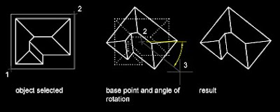
 To stretch with precision, use object snaps, grid snaps, and relative coordinate entry.
 Scale Objects Using a Reference Distance
 Create Rectangular Arrays
  Create Polar Arrays
  The radius of the array is determined by the distance from the specified center point to a reference or base point on the last selected object. You can use the default reference point (usually an arbitrary point that coincides with a snap point), or you can specify a new base point to be used as the reference point.
 You create splines by specifying points. You can close the spline so that the start and endpoints are coincident and tangent.
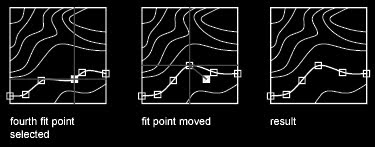
  You can delete fit points of a spline, add fit points for greater accuracy, or move fit points to alter the shape of a spline. You can open or close a spline and edit the spline start and end tangents. Spline direction is reversible. You can change the tolerance of the spline also. Tolerance refers to how closely the spline fits the set of fit points you specify. The lower the tolerance, the more closely the spline fits the points.
  Consider the following example. You have created a spline to represent a geographic contour. Grips are turned on, and you need to move the fourth fit point to increase accuracy. When you select the spline, grips appear at the control points. If you created the spline by fitting it through a set of points, and you haven’t purged this information using the Purge option of the SPLINEDIT command, and you select the Fit Data option, grips appear at the fit points on the selected spline instead of at the control points.