Thursday, December 25, 2014
Tuesday, November 2, 2010
CONTROL DIMENSION VALUES
The numeric values displayed in dimensions can appear in several formats. You can also control how numeric distances are represented.
- Control the Display of Dimension Units
- Round Off Dimension Values
- Suppress Zeros in Dimensions
- Display Lateral Tolerances
Control the display of dimension units
The numeric values of dimensions can be displayed as a single measurement or in two measurement systems. In either case, you can control details of how the numeric values are presented.
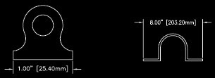
The settings for primary units control the display of the dimension values, including the unit format, the numeric precision, and the decimal separator style. For example, you can enter the diameter symbol as a prefix, as shown in the illustration. Any prefix you specify replaces the prefixes normally used for diameter and radius dimensions (Diameter (unicode 2205 and R, respectively).
 These settings are available on the Primary Units tab of the Dimension Style Manager.
Control the Display of Alternate Units
You can create dimensions in two systems of measurement simultaneously. A common use of this feature is to add feet and inches dimensions to drawings created using metric units. The alternate units appear in square brackets ([ ]) in the dimension text. Alternate units cannot be applied to angular dimensions.
If alternate-units dimensioning is on when you edit a linear dimension, the measurement is multiplied by an alternate scale value that you specify. This value represents the number of alternate units per current unit of measurement. The default value for imperial units is 25.4, which is the number of millimeters per inch. The default value for metric units is 0.0394, which is the number of inches per millimeter. The number of decimal places is specified by the precision value for alternate units.
For example, for imperial units, if the alternate scale setting is the default value, 25.4, and the alternate precision is 0.00, the dimension might look like the following figure.
Tuesday, October 26, 2010
CONTROL THE APPEARANCE OF DIMENSION TEXT
The appearance of dimension text is governed by the text style selected in the Dimension Style Manager, Text tab. You can choose a text style while creating a dimension style and specify a text color and a height independent of the current text style's height setting. You can also specify the gap between base dimension text and the box that surrounds it.
In addition to the prefixes and suffixes specified for primary and alternate units, you can supply your own text as you create a dimension. Because the prefix, suffix, and user-supplied text form a single text string, you can represent tolerance stacks and apply changes to font, text size, and other characteristics using the text editor.
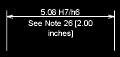
In this example, the primary dimension measurement is 5.08, and the alternate dimension measurement is 2.00. The primary units have the suffix H7/h6, and the alternate units have the suffix inches. At the text prompt, while creating the dimension, you enter the following format string:
<> H7/h6\XSee Note 26\P[ ]
The angle brackets represent the primary units, and the square brackets represent the alternate units. The \X separates text above the dimension line from text below the dimension line. The \P is a paragraph break.
Sunday, October 24, 2010
CONTROL THE LOCATION OF DIMENSION TEXT
 Many of the settings are interdependent. Example images in the Dimension Style Manager are updated dynamically to illustrate how text appears as you change the settings.
Align Dimension Text
Whether text is inside or outside the extension lines, you can choose whether it is aligned with the dimension line or remains horizontal. The following examples show two combinations of these options.
 The default alignment is horizontal dimension text, even for vertical dimensions.
Position Dimension Text Horizontally
The position of the text along the dimension line in relation to the extension lines is referred to as text placement. To place text yourself when you create a dimension, use the Place Text Manually When Dimensioning option on the Fit tab of the Modify/New Dimension Style dialog box. Use the text placement options to automatically place text at the center of the dimension line, at either extension line, or over either extension line.  First and second extension lines are defined by the order in which you specified the extension line origins when you created the dimension. For angular dimensions, the second extension line is counterclockwise from the first. In the following illustrations, 1 is the first extension line origin and 2 the second.
 If you place text manually, you can place the dimension text anywhere along the dimension line, inside or outside the extension lines, as you create the dimension. This option provides flexibility and is especially useful when space is limited. However, the Horizontal alignment options provide better accuracy and consistency between dimensions.
Position Dimension Text Vertically
The position of the text relative to the dimension line is referred to as vertical text placement. Text can be placed above or below or centered within the dimension line. In the ANSI standards, centered text usually splits the dimension line. In the ISO standards, it is usually above or outside the dimension line. For example, ISO standards permit angular dimension text to appear in any of the ways shown. Other settings, such as Text Alignment, affect the vertical alignment of text. For example, if Horizontal Alignment is selected, text inside the extension lines and centered within the dimension line is horizontal, as shown in the leftmost illustration above. The text is horizontal even if the dimension line is not itself horizontal.
Tomorrow we will explore the options to Control the Appearance of Dimension Text, stay tuned...!
Friday, October 15, 2010
CONTROL DIMENSION TEXT
- Fit Dimension Text Within Extension Lines
- Control the Location of Dimension Text
- Control the Appearance of Dimension Text
Fit Dimension Text within Extension Lines
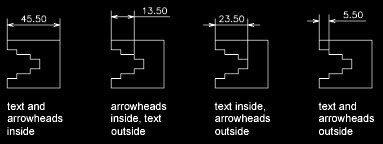
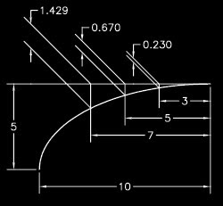
If there is no room for text between the extension lines, you can have a leader line created automatically. This is useful in cases where text outside the extension lines would interfere with other geometry, for example, in continued dimensions. Whether text is drawn to the right or the left of the leader is controlled by the horizontal justification setting on the Text tab of the Modify/New Dimension Style dialog box. Also, you can fit text and arrowheads by changing their size.
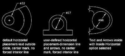
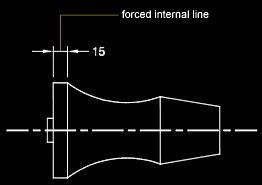 Fit Diameter Dimension Text
You can draw several different diameter dimensions depending on text placement, horizontal settings on the Text tab, and whether you select the Always Draw Dim Line Between Ext Lines options on the Fit tab.
Tomorrow we will explore the options to control the Location of Dimension Text, stay tuned...!
Thursday, October 14, 2010
CONTROL DIMENSION GEOMETRY
Control Dimension Lines
You can control dimension line properties including color, lineweight, and spacing.
You can control several aspects of a dimension line. You can
- Specify color and lineweight for visual effect and plotting
- Suppress the dimension line or, if the dimension line is broken by text, one or both halves

- Control the spacing between successive dimension lines in baseline dimensions

- Control the distance by which the dimension line extends beyond the extension lines for architectural tick (oblique stroke) arrowheads
 Control Extension Lines
 You can control several aspects of the extension lines. You can
- Specify color and lineweight for visual effect and plotting
- Suppress one or both extension lines if they are unnecessary, or if there is not enough space

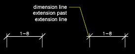
- Specify how far beyond the dimension line that the extension line extends (overshoot)

- Control the extension origin offset, the distance between the extension line origin, and the start of the extension line

- Specify a fixed length for extension lines, as measured from the dimension line toward the extension line origin

- Specify a noncontinuous linetype, typically used for centerlines

- Modify the angle of the extension lines of a selected dimension to make them oblique
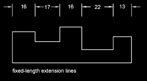
 Fixed-Length Extension Lines
 With the Dimension Style Manager, on the Lines tab, you can specify a dimension style that sets the total length of extension lines starting from the dimension line toward the dimension origin point.
 The extension-line offset distance from the origin will never be less than the value specified by the DIMEXO system variable.
Control Dimension Arrowheads
You can control the arrowhead symbols in dimensions and leaders including their type, size, and visibility.
You can choose from many standard types of arrowheads, or you can create your own arrowheads. Additionally, you can
- Suppress the display of arrowheads, or use one arrowhead only
- Apply a different type of arrowhead to each end of a dimension line
- Control the size of arrowheads
- Flip the direction of an arrowhead using the dimension shortcut menu
Note - Flipped arrowheads maintain their appearance in versions later than AutoCAD 2002. However, if you edit a drawing with flipped arrowheads in a release earlier than AutoCAD 2006, the arrowhead directions will revert to their original orientations.
Customize Arrowheads
You can create your own custom arrowheads.
Arrowheads are stored as block definitions. To use your own arrowhead, provide the name of an existing block definition. For information about creating blocks, see Create Blocks within a Drawing.
Arrowhead sizing relies on the overall dimension scale factor. When you create a dimension, the block is inserted where the arrowheads would normally go. The object's X and Y scale factors are set to arrowhead size x overall scale. The dimension line is trimmed by text gap x overall scale units at each end. To trim the dimension line, the rightmost block is inserted with a zero rotation angle for horizontal dimensioning. The leftmost block is rotated 180 degrees about its insertion point.
If you use paper-space scaling, the scale factor is computed before applying it to the arrowhead size value.
Tomorrow we will explore the tools and options to control the Dimension Text, stay tuned...!
Wednesday, October 13, 2010
COMPARE DIMSTYLES
You can view all the settings in a dimension style. Dimension styles used in externally referenced drawings are differentiated from those defined in your current drawing.
You can list the dimension styles in the current drawing. You can also list all dimensioning system variables and their current status or only the variables affected by a dimension style.
When you list the current status of all dimensioning system variables, any running overrides that apply to the current dimension style are listed. You can also list the differences between a named dimension style and the current dimension style.
Use Externally Referenced Dimension Styles
Externally referenced dimension styles can be examined, but they cannot be modified or made current. You can use an externally referenced dimension style as a template for creating a new dimension style in your current drawing.
Format menu: Dimension Style
Dimension menu: Style
Command line: dimstyle
Compares the properties of two dimension styles or displays all properties of one style. You can print the results of the comparison to the Clipboard, and then paste to other MicrosoftWindowsapplications.
Compare Specifies the first dimension style for the comparison.
Comparison results are displayed automatically under the following headings:
- Description of the dimension style property
- System variable that controls the property
- System variable values of style properties that differ for each dimension style
Results Displays the results of the dimension style comparison. If you compare two different styles, the properties that differ are displayed. If you set the second style to
Print to Clipboard button Copies the results of the comparison to the Clipboard. You can then paste the results to other Windows applications, such as word processors and spreadsheets.
Tomorrow we will learn about controlling Dimension Elements, stay tuned…!