Monday, August 30, 2010

LINES


So we are all set to start the actual CAD, Computer Aided Drafting today. Read thorough and we will draw our First Objects in AutoCAD today itself…! For this we have to open our Assignment3.dwg. Do it!

You can turn off the SNAP and GRID if they are on. We are going to draw 3 Rectangles with the help of Line command which is the First Command of the Draw menu, pull it down and click on Line or type ‘L’ at Command Prompt and press Enter. These rectangles will form our plot boundary for 3 no. of layouts viz. – Ground Floor Plan, First Floor Plan and Terrace Floor Plan. We will draw these 3 rectangles with 3 different methods known as the Coordinate Systems of drafting by AutoCAD.

1. Absolute Coordinate System – With this the geometry is drawn by providing the exact X, Y and Z (if applicable) values of each point that forms the geometry. Most accurate and most difficult method as it is extremely difficult if not impossible to calculate absolute coordinates of every point in the drawing. Best suitable for Survey drawings where you have the ready data in terms of X, Y and Z coordinate.

We will draw the First rectangle with this system. Follow the steps below; your inputs are in RED.

Command: LINE Specify first point: 10',10'
Specify next point or [Undo]: 43',10'
Specify next point or [Undo]: 43',60'
Specify next point or [Close/Undo]: 10',60'
Specify next point or [Close/Undo]: c

Note – ‘C’ will close the current segment with the starting point, in our case 10’, 10’, and could be used for any geometry that needs to be closed at the starting point from the current point.

2. Relative Coordinate System – By this the objects are formed by providing the input with reference to the previous points in the geometry in terms of the distance and angle from the previous point. This is comparatively easier as we don’t need to know the absolute position of the point but its relative position to its predecessor. It comprises the use of two symbols @ (at the rate which denotes the distance from the previous point) and less than (at an angle that specifies the angle at which the next segment is to be drawn I respect of the previous one)

We will draw the Second rectangle with this system. Follow the steps below; your inputs are in YELLOW.

Command: LINE Specify first point: _from Base point: click on point 43', 10' : @10'<0
Specify next point or [Undo]: @33'<0
Specify next point or [Undo]: @50'<90
Specify next point or [Close/Undo]: @33'<180
Specify next point or [Close/Undo]: c

3. Polar Coordinate System – This is the easiest and most popular system by virtue of its being flexible, fast and efficient. In this we will use the combination of Mouse and Keyboard for our inputs. Mouse will provide the Direction of the Vector to be drawn and Keyboard will provide the Dimension that will complete the Vector. With different combinations of Angle Settings, we will be able to draw in various desired directions.

We will draw the Third rectangle with this system. Follow the steps below; your inputs are in
GREEN.

Command: LINE Specify first point: _from Base point: click on lower right corner point of second rectangle : @10'<0
Specify next point or [Undo]: Point the mouse in right direction and type 33'
Specify next point or [Undo]: Point the mouse in up direction and type 50'
Specify next point or [Close/Undo]: Point the mouse in left direction and type 33'
Specify next point or [Close/Undo]: c


Congratulations! We have just drawn THREE Rectangles with Line command within the Limits using all the Coordinate Systems and a Point Filter (remember _from Base point, that’s it!) Tomorrow we will see other commands of the Line group… Stay tuned…!


Sunday, August 29, 2010

OBJECT PROPERTIES

All right so I hope you have understood ‘Layers’ properly and even practiced with a little. Befriend Layers wholeheartedly and you will never have to worry about Organization of your drawing or Properties of the objects within. By the way, if ‘worrying’ is giving you a hard time or making your life miserable, visit my other blog www.ego-wise.blogspot.com and the ideas there may come to your rescue…!

Anyways, getting back on the track, the following general properties are common to most objects. Every object you draw has properties. Some properties are general and apply to most objects; for example, layer, color, linetype, and plot style. Other properties are object-specific; for example, the properties of a circle include radius and area, and the properties of a line include length and angle. Most general properties can be assigned to an object by layer or can be assigned to an object directly.
  • When a property is set to the value BYLAYER, the object is assigned the same value as the layer on which it is drawn.
    For example, if a line drawn on Layer0 is assigned the color BYLAYER, and Layer0 is assigned the color Red, the line is red.
  • When a property is set to a specific value, that value overrides the value set for the layer.
    For example, if a line drawn on Layer0 is assigned the color Blue, and Layer0 is assigned the color Red, the line is blue.

You can display and change the current properties for any object in your drawing in the following ways:

  • View and change the settings in the Layer control on the Layers toolbar and the Color, Linetype, Lineweight, and Plot Style controls on the Properties toolbar. (Most Recommended)
  • Open the Properties palette and view and change the settings for all properties of the object.
  • Use LIST to view information in the text window.
  • Use the ID command to display a coordinate location.
  • Use the Properties Palette

The Properties palette lists the current settings for properties of the selected object or set of objects. You can modify any property that can be changed by specifying a new value.

  • When more than one object is selected, the Properties palette displays only those properties common to all objects in the selection set.
  • When no objects are selected, the Properties palette displays only the general properties of the current layer, the name of the plot style table attached to the layer, the view properties, and information about the UCS.

You can double-click most objects to open the Properties palette when the DBLCLKEDIT command is on (the default). The exceptions are blocks and attributes, hatches, gradient fills, text, multilines, and xrefs. If you double-click any of these objects, an object-specific dialog box displays instead of the Properties palette.

Note – The DBLCLKEDIT command must be on and the PICKFIRST system variable must be on (set to 1, the default) for double-clicking to work.

Color
Specifies the color for objects. Selecting Select Color in the color list displays the Select Color dialog box. You can use the Select Color dialog box to define the color of objects by selecting from the 255 AutoCAD Color Index (ACI) colors, true colors, and color book colors.

Linetype
Specifies the current linetype of the object. The list shows all linetypes in the current drawing.


Linetype Scale
Specifies the linetype scale factor of the object.

Plot Style
Lists NORMAL, BYLAYER, BYBLOCK, plus any plot styles contained in the current plot style table.

Lineweight
Specifies the lineweight of the object. The list shows all available lineweights in the current drawing.

Hyperlink
Attaches a hyperlink to a graphical object. If a description has been assigned to the hyperlink, the description is displayed. If no description has been assigned, the URL is displayed.

Thickness
Sets the current 3D thickness. This property does not apply to all objects.

The objects in an inserted block can retain their original properties, can inherit properties from the layer on which they are inserted, or can inherit the properties set as current in the drawing. Generally when you insert a block, the color, linetype, and lineweight of objects in the block retain their original settings regardless of the current settings in the drawing. However, you can create blocks with objects that inherit the current color, linetype, and lineweight settings. These objects have floating properties.

You have three choices for how the color, linetype, and lineweight properties of objects are treated when a block reference is inserted.

  • Objects in the block do not inherit color, linetype, and lineweight properties from the current settings. The properties of objects in the block do not change regardless of the current settings.
    For this choice, it is recommended that you set the color, linetype, and lineweight properties individually for each object in the block definition: do not use BYBLOCK or BYLAYER color, linetype, and lineweight settings when creating these objects.
  • Objects in the block inherit color, linetype, and lineweight properties from the color, linetype, and lineweight assigned to the current layer only.
    For this choice, before you create objects to be included in the block definition, set the current layer to 0, and set the current color, linetype, and lineweight to BYLAYER.
  • Objects inherit color, linetype, and lineweight properties from the current color, linetype, and lineweight that you have set explicitly, that is, that you have set to override the color, linetype, or lineweight assigned to the current layer. If you have not explicitly set them, then these properties are inherited from the color, linetype, and lineweight assigned to the current layer.
    For this choice, before you create objects to be included in the block definition, set the current color or linetype to BYBLOCK.
Floating properties also apply to nested blocks when the nested block references and the objects they contain use the settings required for floating properties.

That’s all for Object Properties for now. We will discover the other options like Change Property and Match Property as and when required as we progress through the assignment.
Stay tuned…!

Saturday, August 28, 2010

LAYERS - II


Okay, now you have Assignment3.dwg with units, limits set and 7 no. of layers. You might have named them 1, 2, 3 or A, B, C. Today we will make those layers more appropriate, descriptive and in line with our assignment.


Till this point you must have figured out that we are dealing with an Architectural drawing and if you have well read the CAD standards in the opening chapters you might remember the conventions we discussed for naming the layers. It is imperative that we name the layers by sticking to the Standards. To achieve this we will modify our layers in terms of names, colors, etc to suit our exercise.

We will use an 'A' prefix to all our layers to indicate the Architectural discipline. Secondly we will use the names that would make sense with the objects lying on that layer.
So our list of layers would look like -
1. A-Line-Sec – All section lines in the drawing will be drawn on this layer.
2. A-Line-Elv – All elevation lines in the drawing should be drawn on this layer.
3. A-Open-Sec – All openings including Doors and Windows should be drawn on this layer.
4. A-Text-Ann – All the Text and Annotation except dimensions should be drawn here.
5. A-Dim-Arc – All the dimensions in Architectural Units should be put on this layer.
6. A-Plan-Cen – All the Centerlines should be drawn on this layer.
7. A-Fur-Fix – All the Furniture, Fixings and Appliances should be inserted on this layer.
8. A-Stair – All the details in respect of the Staircase should be drawn on this layer.
9. A-Plan-Dtl – Layer for any other details in Plan other than above like symbols, blocks, etc.
10. A-Elev-Dtl – Layer for any other details in Elevation other than above like blocks etc.

Use of Layer 0 (Default Layer of AutoCAD) is not recommended unless for some universal and symbolic elements like, boundary or guidelines.

Once you have entered the names of these 10 Layers make sure that all of them are turned ON, Thawed, Unlocked and have the Plot option available. Let the Layer 0 be current as we will start with Plot boundary which could reside on Layer 0.

We are going to use various Color, Linetype and Lineweight options for our layers to make our Assignment self-explanatory and presentable in view of submission as well as working drawing. Besides it will help us while plotting our drawing, we will find out how. For these settings refer to the picture above. Click on the picture to enlarge it.

Tomorrow we will take a look at the remaining properties of this category of Format like – Color, Linetype, etc. But, for one more time, I would like to underline that if you focus on Layers and understand it properly, you will never have to use these remaining properties individually and I will never recommend their independent use either. You will find out the reason why I am saying this as we progress.

Stay tuned…!

Friday, August 27, 2010

LAYERS

Today we are going to learn the most phenomenal concept of AutoCAD which is instrumental in the organization of the drawing. Layers – the ability of AutoCAD to create, manage and analyze the drawing smartly. Before going into the details let’s first try to understand the concept of layers with some real world examples.

Layers are the equivalent of the overlays used in paper-based drafting. You can consider them as separate transparencies or see-through sheets used to draw different elements by classification of character, property, function and category, forming the complete drawing when put together. This not only helps to visually differentiate items but also facilitates the management of items in terms of selection, modification, visibility and plotting. They are the primary organizational tool in AutoCAD, and you use them to group information by function and to enforce CAD standards.
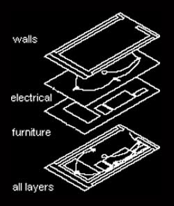
By creating layers, you can associate similar types of objects by assigning them to the same layer. For example, you can put construction lines, text, dimensions, and title blocks on separate layers. You can then control
  • Whether objects on a layer are visible in any viewports
  • Whether and how objects are plotted
  • What color is assigned to all objects on a layer
  • What default linetype and lineweight is assigned to all objects on a layer
  • Whether objects on a layer can be modified

When you begin a new drawing, AutoCAD creates a special layer named 0. By default, layer 0 is assigned color number 7 (white or black depending upon your background color), the CONTINUOUS linetype, a lineweight of Default (the default setting is .01 inch or .25 mm), and the NORMAL plot style. Layer 0 cannot be deleted or renamed.

Format – Layers can make a layer current, add new layers, delete layers and rename layers. You can assign properties to layers, turn layers on and off, freeze and thaw layers globally or by viewport, lock and unlock layers, set plot styles for layers, and turn plotting on and off for layers. You can filter the layer names displayed in the Layer Properties Manager, and you can save and restore layer states and properties settings.

Named Layer Filters determines which layers to display in the list of layers. You can filter layers based on whether they're xref-dependent, or whether they contain objects. You can also filter layers based on name, visibility, color, linetype, lineweight, plot style name, whether they are plotted, or whether they are frozen in the current viewport or in new viewports.

[...] Button displays the Named Layer Filters dialog box.

Invert Filter displays layers based on the opposites of the criteria in a named layer filter. Layers that fit the inverse criteria are displayed in the layer name list.

Apply to Object Properties Toolbar displays in the Object Properties toolbar only layers that match the current filter. The layer list tooltip on the Object Properties toolbar displays the filter status of layers in the drawing. (To display the layer list tooltip, position the pointing device over the layer list on the Object Properties toolbar.)

New creates a new layer. After you choose New, the list displays a layer named LAYER1. You can edit this layer immediately. To create multiple layers more quickly, you can select a layer name for editing and enter multiple layer names separated by commas.

If you create a new layer, the new layer inherits the properties of the currently selected layer in the layer list (Color, On/Off state, and so on). To create layers with default settings, make sure that there are no selected layers in the list or that you select a layer with default settings before beginning layer creation.

Current sets the selected layer as the current layer.

Delete deletes selected layers from the drawing file definition. You can delete only unreferenced layers. Referenced layers include layers 0 and DEFPOINTS, layers containing objects (including objects in block definitions), the current layer, and xref-dependent layers. Layers that don't contain objects (including objects in block definitions), are not current, and are not xref-dependent can be deleted by using the PURGE command. We will see it in detail at later stage.

Warning! Be careful about deleting layers if you are working on a drawing in a shared project or one based on a set of layering standards.

Show/Hide Details controls whether the Details section is displayed in the Layer Properties Manager.

Save State displays the Save Layer States dialog box, in which you save layer state and layer properties settings of all layers in a drawing. You can choose which layer states and properties that you want to preserve. You save a layer state by assigning it a name.

If one or more of these settings are cleared, the Layer Properties Manager does not restore those settings. Any layer states saved in a drawing that is inserted in your current drawing as a block are also added to the current drawing. The saved layer states of referenced drawings (xrefs) are not accessible from the current drawing. If you use WBLOCK to create a new drawing from the current drawing, saved layer states are preserved only if you specify Entire Drawing as the source in the Write Block dialog box. These saved layer states will refer only to layers that contain objects.

Restore State displays the Layer States Manager, in which you can manage named layer states.

List of Layers displays layers and their properties. To modify a property, click its icon. To quickly select all layers, right-click and use the shortcut menu.

Names display the names of the layers. You can select a name and then click and enter a new name. The name can include letters, numbers, blank spaces, and any special character not used by Microsoft® Windows® or AutoCAD for other purposes.

On/Off will turn layers on and off. When a layer is on, it is visible and available for plotting. When a layer is off, it is invisible and not plotted, even if Plot is on.

Freeze/Thaw in All Viewports freezes selected layers in all viewports. You can freeze layers to speed up ZOOM, PAN, and many other operations; improve object selection performance; and reduce regeneration time for complex drawings. AutoCAD does not display, plot, hide, render, or regenerate objects on frozen layers. Freeze the layers you want to be invisible for long periods. When you thaw a frozen layer, AutoCAD regenerates and displays the objects on that layer. If you plan to switch between visible and invisible states frequently, use the On/Off setting. You can freeze layers in all viewports, in the current layout viewport, or in new layout viewports as they are created.

Lock/Unlock locks and unlocks the layers. You cannot edit objects on a locked layer. Locking a layer is useful if you want to view information on a layer for reference but do not want to edit objects on that layer.

Color changes the color associated with the selected layers. Clicking the color name displays the Select Color dialog box.

Linetype changes the linetype associated with the selected layers. Clicking any linetype name displays the Select Linetype dialog box.

Lineweight changes the lineweight associated with the selected layers. Clicking any lineweight name displays the Lineweight dialog box.

Plot Style changes the plot style associated with the selected layers. If you are working with color-dependent plot styles you cannot change the plot style associated with a layer. Clicking any plot style displays the Select Plot Style dialog box.

Plot/Don't Plot controls whether the selected layers are plotted. If you turn off plotting for a layer, the objects on that layer are still displayed. Turning off plotting for a layer affects only visible layers in the drawing (layers that are on and thawed). If a layer is set to plot but is currently frozen or off in the drawing, AutoCAD does not plot the layer. Turning off plotting for layers containing reference information such as construction lines can be useful.

Current VP Freeze (available only from a layout tab) freezes selected layers in the current layout viewport. You can freeze or thaw layers in the current viewport without affecting layer visibility in other viewports. Frozen layers are invisible; they are not regenerated or plotted. Thawing restores the layer's visibility.

New VP Freeze (available only from a layout tab) freezes selected layers in new layout viewports. For example, freezing the DIMENSIONS layer in all new viewports restricts the display of dimensions on that layer in any newly created layout viewports but does not affect the DIMENSIONS layer in already existing viewports. If you then create a viewport that requires dimensions, you can override the default setting by changing the current viewport setting.

Details displays an extension of the Layer Properties Manager with alternative access to properties and additional options.

Phew! That’s the end of the list for Layers. You might think this really is a mighty list but believe me, if once, only once, you took the effort to understand it thoroughly you will thank yourself in the future when you will reap the benefits! This one concept of layers and comprehending it’s maximum, if not all, little details will save you hours of sleepless nights when you will work with huge drawings containing thousands of objects and elements.

For the practical exercise of layers, open Assignment3 and create 7 no. of layers with names and colors of your choice. We will modify them appropriately in tomorrow’s session.

Stay tuned…!

Thursday, August 26, 2010

LIMITS and THICKNESS

Now as we have set the Units for our assignment, we can go ahead with limits. To understand the concept of limits let us take a real world example. Assume that you are supposed to build a house or any structure for that matter, where would you start? Identifying, locating and demarcating a Site or Plot for your proposed construction, isn’t it? You can not just start building your structure anywhere on the open land. Similarly although Model Space is infinite and available, we need to restrict some area for our assignment in this enormous space. This is achieved by setting the limits.

Although it is not mandatory, it is good idea to set limits of our assignment in view of use of GRID and structure of drawing. It helps a great way to work within limits, especially in the initial times of practice. That way we can better understand the concepts of Coordinates and Composition. Secondly limits would come handy in case you need to plot your drawing from Model Space itself, not recommended though!

Setting the limits higher than our maximum spread of drawing is always advisable for having enough space to facilitate the arrangement and composing of the drawing elements.

For our assignment we will set the limits to 400’, 300’ so that we have enough space for all our 5 elements. To do this click on Format – Drawing Limits.
This will return a prompt
Specify lower left corner or [ON/OFF] : Specify a point, enter on or off, or press ENTER
Specify lower left corner or [ON/OFF] <0'-0",0'-0">:
Specify upper right corner <1'-0",0'-9">: 400',300' press enter

On turns on limits checking. When limits checking is on, you cannot enter points outside the grid limits. Because limits checking tests only points that you enter, portions of objects such as circles can extend outside the grid limits.

Note – LIMCHECK System Variable controls the creation of objects outside the grid limits. When set to ‘0’ objects can be created outside the limits and when set to ‘1’ objects cannot be created outside the limits.

Set the GRID and SNAP spacing to 5’ and turn them on. Draw a Rectangle from 0,0 to 400’,300’ and click View – Zoom – All. Your screen should look like one in the picture. Save your drawing in D drive – Exercises folder – Chapter1 subfolder with the name Assignment3.dwg.


The last setting in this group of three under Format menu is Thickness.
Thickness is a property of certain objects that gives them a 3D appearance.

The 3D thickness of an object is the distance of that object extended, thickened, above or below its location in space. Positive thickness extrudes upward in the positive Z direction; negative thickness extrudes downward (negative Z). Zero (0) thickness means that there is no 3D thickening of the object. The Z direction is determined by the orientation of the UCS at the time the object was created. Objects with a non-zero thickness can be shaded and can hide other objects behind them.


The thickness property changes the appearance of the following types of objects:

  • 2D solids
  • Arcs
  • Circles
  • Lines
  • Polylines (including spline-fit polylines, rectangles, polygons, boundaries, and donuts)
  • Text (only if created as a single-line text object using an SHX font)
  • Traces
  • Points

Modifying the thickness property of other types of objects does not affect their appearance. You can set the default thickness property for new objects you create by setting the THICKNESS system variable. Change the thickness property of an existing object using the Properties palette. The 3D thickening is applied uniformly on an object: a single object cannot have different thicknesses for its various points.

You may need to change the 3D viewpoint to see the effect of thickness on an object.

Tomorrow we will learn the fundamental and significant concept of AutoCAD – Layer.

Meanwhile practice with limits and thickness. Stay tuned..!

Wednesday, August 25, 2010

UNITS

Okay, so let’s get started with our Assignment…!

Before starting let’s understand that we will use the Model Space for Drafting / Modeling and Paper Space for Page Setup and Plotting. In other words we are not going to set any boundaries, except limits, in the Model Space and will not restrict ourselves to any Paper Size, Scale or Viewports.

Don’t even think of Size of the drawing in terms of Spread as long as we are working in Model Space. We will draft / model everything to the real world or true scale i.e. 100’ would be drawn as 100’ without any scaling down. As we have already learnt there is no size limit in Model space and we can draw anything as big as it gets, instead of worrying about the size and scale of the drawing we will focus on making the drawing Organized, Composed and Smart.

Right, now to begin with the first thing we should set is the Units. Drawing units would instruct AutoCAD about the type of measurements we are going to use. To achieve this click on Format – Units, a dialogue box of Drawing Units will open. In this dialogue box there are 4 sections –

1. Length specifies the current unit of measurement and the precision for the current units.

Type sets the current format for units of measure. The values include Architectural, Decimal, Engineering, Fractional, and Scientific. The Engineering and Architectural formats produce feet-and-inches displays and assume that each drawing unit represents one inch. The other formats can represent any real-world unit.

Precision sets the number of decimal places or fractional size displayed for linear measurements.

2. Angle specifies the current angle format and the precision for the current angle display.

Type sets the current angle format.
Precision sets the precision for the current angle display.

The following conventions are used for the various angle measures: decimal degrees appear as decimal numbers, grads appear with a lowercase g suffix, and radians appear with a lowercase r suffix. The degrees/minutes/seconds format uses d for degrees, ' for minutes, and " for seconds – 123d45'56.7"

Surveyor’s units show angles as bearings, using N or S for north or south, degrees/minutes/seconds for how far east or west the angle is from direct north or south, and E or W for east or west – N 45d0'0" E

The angle is always less than 90 degrees and is displayed in the degrees/minutes/seconds format. If the angle is precisely north, south, east, or west, only the single letter representing the compass point is displayed.

Clockwise calculates positive angles in the clockwise direction. The default direction for positive angles is counterclockwise. When prompted for an angle, you can point in the desired direction or enter an angle regardless of the setting specified for Clockwise.

3. Insertion Scale controls the unit of measurement for blocks and drawings that are inserted into the current drawing. A block or a drawing that is created with units that are different from the units specified with this option is scaled when inserted. The insertion scale is the ratio of the units used in the source block or drawing and the units used in the target drawing. Select Unitless to insert the block without scaling it to match the specified units.

Note – In the Options dialog box, User Preferences tab, the Source Content Units and Target Drawing Units settings are used when, either in the source block or the target drawing, Insertion Scale is set to Unitless.

4. Sample Output displays an example of the current settings for units and angles.

Direction – Displays the Direction Control Dialog Box

Defines the angle for 0 degrees and specifies the direction in which angles are measured. When prompted for an angle, you can locate a point in the desired direction or enter an angle.

Base Angle sets the direction of the zero angle. The following options affect the entry of angles, the display format, and the entry of polar, cylindrical, and spherical coordinates.

East specifies the compass direction east (the default).
North specifies the compass direction north.
West specifies the compass direction west.
South specifies the compass direction south.
Other specifies a direction different from the points of the compass.

Angle specifies a value for the zero angle when Other is selected. You can specify the angle by entering a value.

Pick an Angle Button defines the zero angle in the graphics area based on the angle of an imaginary line that connects any two points you specify with the pointing device. Available only when Other is selected.

For our assignment set the units to Architectural and precision to 0’0” and leave the rest as it is. Once the Units are set we can proceed to Limits, which we will see tomorrow.

Stay tuned…!

Tuesday, August 24, 2010

ASSIGNMENT

Alright! We have managed everything and are ready for our ‘what’s cooking?’ experiment and have the ingredients and tools in front of us and all set to prepare our recipe called CADVENTURE…!

Since it’s a feast we will have to prepare a proper 7 course supper…!
First CourseFormat and Tools – the appetizers to start it right for handling and consuming the items properly
Second CourseDraw and Modify – the main course with supplements to serve our appetite
Third CourseView – to help us gazing around the stuff
Fourth CourseInsert – for adding spice and fun to enrich the experience
Fifth CourseDimension – to scale what we should have and what we had
Sixth CourseEdit – the optional pickles and salads as per choice
Seventh CourseFile – the deserts and drinks to help digestion

The name of our feast is ‘Assignment3.dwg’ with 5 main ingredients –
1. Architectural layout plans of a Bungalow – 3 Nos.
2. A Centerline Plan for the same – 1 Nos.
3. Elevations of the structure – 2 Nos.
4. A Typical Section of the structure – 1 Nos.
5. Accessories like Template, Legend or Notes Table – 1 Nos.

In the following sessions our line of action will be – Learn, Study and understand the Concept in form of input and practice its application in form of commands in our assignment appropriately.

Exercise – To design, draft and present drawings set for a proposed bungalow on a plot size of 40’ x 25’
Requirements –
1. 1 Living Room
2. 1 Kitchen
3. 1 Family Room
4. 1 Children Bedroom
5. 1 Master Bedroom
6. 1 Guest Room

To start with, today just study the final output as shown in the picture (click on the picture to open an enraged view in the new window) and we will start working on it from tomorrow. Our objective is to achieve the similar or better output than what is displayed.

Try to understand the details of the exercise and we will actual work from tomorrow…
Stay Tuned…!

Monday, August 23, 2010

LWT and MODEL

It’s so far so good, I believe…! I also believe you have utilized the weekend for practicing whatever learnt till this point. I hope you don’t have any confusion or doubt about the basics of AutoCAD and it’s interface.

Today we will conclude the Interface and Drafting Settings part so that we can proceed to Drawing Preparation from tomorrow. Today it is comparatively easy as we are going to deal with just TWO last tabs of last toolbar – LWT and MODEL.

LWT is the abbreviation for Line Weight what AutoCAD refers to as a single word Lineweight. Basically lineweight is meant for Plotting. This setting instructs AutoCAD about the width or thickness or boldness with which the vector should be drawn. Although by default lineweight is zero it doesn’t mean that the object drawn would be invisible. In the real world context what it means id the minimum pen width available. For e.g. if you have minimum pen width of 0.1 it is treated as zero and if you have 0.05 pen width available that would be zero. The normal standard pen widths used are 0.1, 0.2, 0.3, 0.4, 0.5 and 0.7.

Setting different Lineweights for different objects makes it easy to differentiate between them in terms of type, character, property or level, when plotted provided that proper plot settings are used. We will learn each and every minor detail about it in due course. For now all we should understand is – LWT turns the display of Lineweights ON and OFF. When the Lineweights are turned on, while using the viewing commands like ZOOM, objects regenerate continuously and may give a distorted or mangled display that can cause problems while working. This is the reason why Lineweights are by default turned OFF. And it is even recommended not to keep them on unless for a quick preview and analysis.


MODEL tab has a different purpose than one in the Space Tabs section. We have already learnt about the Model and Layout Tabs which are meant for switching between the spaces. When you switch to Layout Tab from Model Space the scenario immediately changes to 2D drafting from 3D modeling and the ‘Z’ axis disappears. Now imaging a situation where you need to work in the Model Space for some reason without leaving the Layout Tab. What I mean is you want to do some editing in your Layout Drawing with some Model Space facilities. This can be done by using this last MODEL tab on the Drafting Settings Toolbar. You can easily switch between Paper Space and Model Space within the Layout with this button.

I know it is little difficult to understand theoretically. Why don’t you try it ‘Hands On’ as they say? This will serve two purposes –
1. You will make yourself familiar with the ‘AutoCAD Environment’ as I like to call it and
2. You will be in a better position to ‘Switch’ when we will need in real time…!


You can take a break, do some breathing exercise or meditation of any sort that you are habitual to and sit back and relax for a while. With this we have finished the FIRST section of AutoCAD interface and settings, for now. Once you master it you’ll find yourself working more efficiently and productively as we progress.

Next is Preparation for our First Drawing Assignment before we draw the first line of our Assignment3. Tomorrow we will see what appetizers we should order before the Main Course…

Stay Tuned…!

Saturday, August 21, 2010

OSNAP

Today we will try to learn a very important tab called OSNAPObject Snap.
Object Snap Tab controls running object snap settings. With running object snap settings you can specify a snap point at an exact location on an object. When more than one option is selected, the selected snap modes are applied to return a point closest to the center of the aperture box. Press TAB to cycle through the options.

To understand it better we will take some examples –
1. A Point has a Single Object Snap – A Node
2. A Line has 3 Object Snaps – Two Endpoints and One Midpoint
3. A Rectangle has 8 Object Snaps – Four Endpoints and Four Midpoints
4. A Circle has 5 Object Snaps – One Center point and Four Quadrant Points

Object Snap On turns running object snaps on and off. The object snaps selected under Object Snap Modes are active while object snap is ON.

Object Snap Tracking On turns object snap tracking on and off. With object snap tracking, the cursor can track along alignment paths based on other object snap points when specifying points in a command. To use object snap tracking, you must turn on one or more object snaps.

Object Snap Modes lists object snaps that you can turn on as running object snaps.


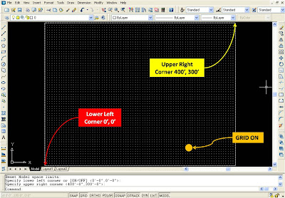
Endpoint snaps to the closest endpoint of an arc, elliptical arc, line, multiline, polyline segment, spline, region, ray or to the closest corner of a trace, solid, or 3D face.

Midpoint snaps to the midpoint of an arc, ellipse, elliptical arc, line, multiline, polyline segment, region, solid, spline, or xline.

Center snaps to the center of an arc, circle, ellipse, or elliptical arc.

Node snaps to a point object, dimension definition point, or dimension text origin.

Quadrant snaps to a quadrant point of an arc, circle, ellipse, or elliptical arc.


Intersection snaps to the intersection of an arc, circle, ellipse, elliptical arc, line, multiline, polyline, ray, region, spline, or xline. Extended Intersection is not available as a running object snap.

Intersection and Extended Intersection do not work with edges or corners of 3D solids.

Note – You might get varying results if you have both the Intersection and Apparent Intersection running object snaps turned on at the same time.

Extension causes a temporary extension line or arc to be displayed when you pass the cursor over the endpoint of objects, so you can specify points on the extension.

Insertion snaps to the insertion point of an attribute, a block, a shape, or text.

Perpendicular snaps to a point perpendicular to an arc, circle, ellipse, elliptical arc, line, multiline, polyline, ray, region, solid, spline, or xline. Deferred Perpendicular snap mode is automatically turned on when the object you are drawing requires that you complete more than one perpendicular snap. You can use a line, arc, circle, polyline, ray, xline, multiline, or 3D solid edge as an object from which to draw a perpendicular line. You can use Deferred Perpendicular to draw perpendicular lines between such objects. When the aperture box passes over a Deferred Perpendicular snap point, an AutoSnap tooltip and marker are displayed.

Tangent snaps to the tangent of an arc, circle, ellipse, elliptical arc, or spline. Deferred Tangent snap mode is automatically turned on when the object you are drawing requires that you complete more than one tangent snap. For example, you can use Deferred Tangent to draw a line that is tangent to two arcs, polyline arcs, or circles. When the aperture box passes over a Deferred Tangent snap point, a marker and an AutoSnap tooltip are displayed.

Note – When you use the From option in conjunction with the Tangent snap mode to draw objects other than lines from arcs or circles, the first point drawn is tangent to the arc or circle in relation to the last point selected in the drawing area.

Nearest snaps to the nearest point on an arc, circle, ellipse, elliptical arc, line, multiline, point, polyline, ray, spline, or xline.

Apparent Intersection snaps to the visual intersection of two objects that are not in the same plane but may appear to intersect in the current view. Extended Apparent Intersection is not available as a running object snap. Apparent and Extended Apparent Intersection do not work with edges or corners of 3D solids.

Note – You might get varying results if you have both the Intersection and Apparent Intersection running object snaps turned on at the same time.

Parallel draws a vector parallel to another object whenever you are prompted for the second point of a vector. After specifying the first point of a vector, if you move the cursor over a straight line segment of another object, the point is acquired. When the path of the object you create is parallel to the line segment, an alignment path is displayed, which you can use to create the parallel object.

Select All turns on all object snap modes.
Clear All turns off all object snap modes.

Alright, it’s getting more and more technical and specific, isn’t it? But after all that’s what AutoCAD is all about..! Okay, before you have a spinning head and you start it banging against the monitor, here is good news… Have a break for a day (I need it too!) and Monday we will explore the last TWO (trust me) tabs LWT and MODEL to finish this. Then we can proceed to more interesting and interactive part of Drawing Preparation…!

See you on Monday, stay tuned…!

Friday, August 20, 2010

POLAR

So we have mastered the SNAP and GRID settings of AutoCAD. And by the time you must have got a fair idea of Limits as well. If not, don’t worry, we will come back to it later…

Today we will try to understand next FOUR tabs ORTHO, POLAR, OTRACK and DYN, i.e. Dynamic Input. These FOUR tabs are correlated and hence needs to be addressed simultaneously.

Alright now, click on the ORTHO tab or press F8 once and you will turn on the ORTHO mode. In ORTHO mode you will be able to draw lines only in X and Y direction i.e. horizontal and vertical. This mode ensures that no angular, incline or non-ortho line is drawn. This is great when you want to work with orthographic objects only and don’t want to leave any room for mistake.

Note – There is no ‘setting’ for ORTHO just turn it ON and OFF by pressing F8.

Next is Polar tab which, unlike ORTHO, allows the user to draw lines at desired angles and even set the angles. This can be turned on and off by pressing F10. To adjust the settings, right-click on the tab and click on ‘settings’. This will open the Drafting Settings dialogue box, common for Snap and Grid, Polar Tracking, Object Snap and Dynamic Input. In the Polar Tracking tab, you have options for –

1. Turning Polar Tracking On and OFF

2. Polar Angle Settings with incremental angle and additional Angles
  • Increment Angle sets the polar increment angle used to display polar tracking alignment paths. You can enter any angle, or select a common angle of 90, 45, 30, 22.5, 18, 15, 10, or 5 degrees from the list.
  • Additional Angles makes any additional angles in the list available for polar tracking. Additional angles are absolute, not incremental.
  • List of Angles lists the additional angles that are available. To add new angles, click New. To remove existing angles, click Delete. ‘New’ adds up to 10 additional polar tracking alignment angles. ‘Delete’ deletes selected additional angles.

3. Object Snap Tracking Settings sets options for object snap tracking.

  • Track Orthogonally Only displays only orthogonal (horizontal/vertical) object snap tracking paths for acquired object snap points when object snap tracking is on.
  • Track Using All Polar Angle Settings applies polar tracking settings to object snap tracking. When you use object snap tracking, the cursor tracks along polar alignment angles from acquired object snap points.

4. Polar Angle Measurement sets the basis by which polar tracking alignment angles are measured.

  • Absolute bases polar tracking angles on the current user coordinate system (UCS).
  • Relative to Last Segment bases polar tracking angles on the last segment drawn.

Dynamic Input tab controls pointer input, dimension input, dynamic prompting, and the appearance of drafting tooltips.

  • Enable Pointer Input turns on pointer input. When pointer input and dimensional input are both turned on, dimensional input supersedes pointer input when it is available.
  • Pointer Input displays the location of the crosshairs as coordinate values in a tooltip near the cursor. When command prompts for a point, you can enter coordinate values in the tooltip instead of on the command line.
  • Dimension Input displays a dimension with tooltips for distance value and angle value when a command prompts for a second point or a distance. The values in the dimension tooltips change as you move the cursor. You can enter values in the tooltip instead of on the command line.
  • Dynamic Prompts displays prompts in a tooltip near the cursor when necessary in order to complete the command. You can enter values in the tooltip instead of on the command line.

Drafting Tooltip Appearance displays the Tooltip Appearance dialog box.

Note – OTRACK tab is an alternative for Polar Tracking and can be used to set Polar Tracking. Phew! It is quite a list, isn’t it? But don’t panic, you can go at your own pace to understand it all in detail. Secondly, exercise is a best option for getting acquainted with newly learned tools. Go ahead and try to draw at least 5 lines with each setting we have just learned. You should have at least 50 lines that will comprise your Assignment2.

Tomorrow we will talk about OSANP, stay tuned…!

Thursday, August 19, 2010

SAVE

Yesterday we have successfully completed the First Assignment with AutoCAD. Now the second equally important thing after finishing the assignment is saving it for archival as well as retrieval for future use. Before saving any file let’s get an idea of PATH.

PATH, in computer language, is referred to the physical address of any digital file created with any application. Any computer has two types of storage devices – Temporary and Permanent. Floppy, CD, Flash Drives etc. are the examples of the temporary storage devices while Hard Disk is the example of the permanent storage device. Owing to their capacity, structure and nature, temporary storage device are good and most suitable for transferring of the data from one place to another but are inappropriate for long-term retention of data. Hence it is strongly recommended to SAVE the files on the Hard Disk.

Typically any Hard Disk has Partitions creating different drives. It is universal to have at least two drives, generally ‘C’ and ‘D’. It is advisable to install all your operating systems and applications on ‘C’ drive and all your work on the ‘D’ drive as it is less vulnerable to Virus Attacks and System Crashes, as compared to ‘C’. Why I say so is because whatever WE have created is UNIQUE and hence most valuable and thus needs to be protected and safeguarded. I don’t mean to say that OS or Applications are not important. Of course they are. But you can always ask for help and backup if you need to regain them.

So consider your ‘D’ drive as your City’s name. Now you cannot reach the address with city’s name alone. You will need the name of the area – for this purpose create a folder on the ‘D’ drive with a suitable name. For e.g. ‘Exercises’ (When you will work professionally it is common practice to create the folder in the name of the Project). Okay, we have reached in that particular area. Here you will need more specific information like the Lane, Road or Gully name. Create a subfolder within the folder ‘Exercises’, for our purpose we will name it chapter-wise, so name it ‘Chapter1’. In this particular lane you will need the name / no. of the building. This is our particular file. (For the above exercise minimize AutoCAD window and open Explorer window)

Now, come back to AutoCAD and click on File – Save, this will open the ‘Save Drawing As’ dialogue box. In the ‘Save in’ field locate D drive – Exercises folder – Chapter1 subfolder, all by double-clicking on the respective names. In the File name field type Assignment1 and click on Save next to it. Great! You have saved your first drawing file in a organized and effective manner. Congratulations! Don’t worry about the Files of type option as of now. We will learn about it’s purpose and method as we progress.

Path for your drawing is file://comp1d:/Exercises/Chapter1/Assignment1.dwg.

This was our first step to understanding and working with AutoCAD interface. We will quickly review what we have learnt during this assignment in a summarized form.
  • Limits and GRID has a relation and both facilitate the drafting process.
  • Zoom – All applies the Limits in the space.
  • Grid and Snap work only in rectangular fashion, therefore it is most useful and efficient while working with rectangular patterned objects like staircase.
  • GRID and SNAP spacing could be different but should belong to the same table.
  • Line command has two prompts – First Point and Next Point, which is repeated as long as you continue drawing the line. It could be ended by pressing enter or ‘C’ and enter.
  • It is interesting to work with AutoCAD…!

Practice drawing shapes in the picture with GRID and SNAP ON

Although we worked with GRID and SNAP ON in this assignment, we were able to draw diagonal lines as well. Can we restrict ourselves to horizontal/vertical lines only?

We will see tomorrow. Stay tuned…!

Wednesday, August 18, 2010

SNAP & GRID

Today let’s study the bottommost horizontal bar at center that is meant for Drafting Setting.

Before getting into these TABS let us understand that AutoCAD works on the philosophy of Co-ordinate Systems. Being a vector-based application every entity in AutoCAD is a Vector – an object with Dimension and Direction. To achieve this it is imperative to LOCATE the points forming that object or geometry. There are different means of locating the points in a space or drawing, most common and popular being the coordination.

In AutoCAD every point or location is referred in terms of X, Y and Z coordinates. As we already know Origin is a point in the space with 0, 0, 0 values for X, Y and Z respectively. X is the displacement of a particular point in horizontal direction from the origin, Y is the displacement of that point in vertical direction from the origin and Z is the displacement of it in the direction perpendicular to the XY plane. Z is also referred as the Elevation or Level for this reason. Any point that is elevated from XY plane in the upward direction has a positive nonzero Z value and if it is dropped down from XY plane it is supposed to have some negative nonzero Z value.

Alright, now as we have understood the concept of XY Plane, Origin and Coordinates, let’s move on to learn the first TWO tabs of Drafting Setting namely SNAP and GRID.

There are some basic assumptions for using SNAP and GRID.

  1. SNAP and GRID should always be used in unison as only one of them would be ineffective.
  2. GRID is a matrix of DOTS forming a square or rectangle depending upon the limits set.
  3. Limits – the user specified area in the space – and GRID are relative. This means that if you set limits to a high value, say 12000, 9000 and try to set the GRID with value 1, it could not be displayed as it would become too dense and AutoCAD will warn you about the same.
  4. SNAP and GRID work only in X and Y direction. By this what I mean is it is impossible to set the SNAP and GRID in a triangular, circular or any other fashion, for that matter, other than linear.
  5. Although AutoCAD by default forms a square GRID with identical X and Y values, it is possible to set different X and Y values for GRID as well as SNAP, provided they blong to the same table. You can not set GRID 5, 5 and SNAP 3, 3.

Okay, now let’s try to practice it by applying Limits, turning ON the GRID and SNAP.
Follow the steps below to complete the exercise in the picture.

  1. From the Format menu select the 'Drawing Limits' and turn them ON by entering values 0, 0 for the Lower Left Corner and 6000, 5400 for the Upper Right Corner.
  2. From the View menu select 'Zoom – All' to ‘Apply’ the limits.
  3. Right Click on the SNAP or GRID button and select Settings
  4. In the Drafting Settings dialogue box put the values as shown - In the Grid, enter 150 in X spacing and 150 in Y spacing fields. In Snap, enter 300 in X spacing and 150 in Y spacing fields.
  5. Check the boxes against Snap On (F9) and Grid On (F7) to turn ON Snap and Grid.
  6. Type ‘L’ at the command prompt to initiate the Line command.
  7. Specify 300,300 as the start point.
  8. To draw the first step, move the mouse upward and click at the first point where it locks. Move the mouse rightward and click at the first point where it locks.
  9. Repeat step 8 for 17 times to draw 17 more steps.
  10. Move the mouse downwards and click to form the closure.
  11. Move the mouse diagonally downwards till it is in line with the start point and below top of the first step and click to form the waist of the stair.
  12. Type ‘C’ and enter to close and finish your staircase.

Congratulations! You have just completed the First Assignment with AutoCAD!
Tomorrow we will explore the Saving Options and analyze our First Assignment.

Stay Tuned…!

Tuesday, August 17, 2010

TOOLBARS

Today let’s talk about TWO horizontal bars below the Menu Bar – Standard Toolbar and Object Properties Bar and TWO vertical Floating Toolbars.

Standard Toolbar

It is obvious from the name that this is the most common standardized toolbar any Windows application has and AutoCAD is no exception. There are some tasks and operations with any computer file those are so routine and inevitable that they are almost universal. These include File Handling Options like – New, Open, Save, Plot, etc. Quick editing commands like Undo and Redo. What AutoCAD Standard Toolbar has different are the commands like –

  • Match Properties – Where you can match physical properties of the source and new object.
  • Block Editor - with which you can edit BLOCKs in place.
  • Viewing commands like Zoom, Pan and alike.
  • Properties, Designcenter, Sheet Set Manager, Markup Set Manager and QuickCalc for calculations.
  • Format toolbar with Text Style, Dimension Style and Table Style settings.
Object Properties Toolbar

This is AutoCAD-specific Toolbar which is divided FIVE distinct parts – each for managing a specific property. Although properties like Color, Linetype, Lineweight, etc could be assigned, changed and managed individually for all the objects in the drawing, IT IS NOT AT ALL RECOMMENDED unless absolutely and exceptionally required. Why I say so is because AutoCAD provides a phenomenal and intelligent concept of LAYER from where any and all physical properties of the objects in the drawing could and should be controlled. This not only facilitates the drawing assembly but also makes the drawing organized, structured and smart providing administrative governing of drawing in view of efficiency, analysis and management. The Five parts of the object properties toolbar are

  • Layer – The foremost and major element in any drawing about which we will learn in detail like, it’s structure, components, behavior and effect as whole, in due course.
  • Color – This Tab offers the control of Color of objects in the drawing.
  • Linetype – From here user can assign, change or manage the Linetype of any object.
  • Lineweight – Useful for setting the lineweights of the objects in the drawing.
  • Plotstyle - This instructs AutoCAD about the Plot settings like color or mono, what lineweights to plot, etc.

Floating / Docked Toolbars

These are the additional toolbars that can be adjusted as per the requirement and convenience of the user. Although AutoCAD has enough toolbars to fill up the entire screen it is neither recommended to turn on all the toolbars nor would it be workable. For this reason AutoCAD, by default, makes available TWO basic toolbars, one at each side of the screen – Draw and Modify. As their names suggest, these are the toolbars those hold the maximum no. of frequently used commands.

There could be more toolbars turned on in place of / in addition to these toolbars according to the stage and purpose of the session. For e.g. –

  • If the session is started for analysis you might want to turn on the Inquiry toolbar OR
  • If you are working with 3D modeling, consider turning on 3D Commands or UCS toolbar
Tomorrow we will try to understand the Drafting Settings.
Stay Tuned...!

Monday, August 16, 2010

MENU BAR

We have already learnt about the different bars in the AutoCAD screen. Today let’s get a closer look at their respective components and strategy thereof.

The topmost bar is the Title bar holding titles, as we’ve already know. There’s nothing more about it.

The Second-in-position bar immediately under the title bar is our Menu Bar which will serve us with the different menus, either standard or special, depending upon the user’s appetite, throughout our CAD session. These menus also can be customized with a little bit of expertise and much more experience. Let’s keep it for the Expert Mode when we will reach there…!

Every menu has a drop-down list which is divided into categories separated by horizontal grey lines. The logic behind this categorization is simple – the commands that are similar in character and behavior are clubbed together in a group. This also makes the interface lucid and clutter free to work with.

Secondly, the commands those have further subcommands or specifications, are shown with a small triangular arrow pointing right in line of that command at right edge of the Menu box. This is repeated at the subcommand if it also has some sub-options.

Note – In the drop-down menu, wherever you see a small triangular arrow pointing right at the end of any command, remember that it indicates further subcommand or sub-option and this is to facilitate the accuracy and precision of your drawing by providing specifications to the last detail.


Okay, let’s have an overview of the feast we are being presented within this CAD-Session…!
  1. File – This menu helps to create, manage and retrieve AutoCAD files. The categories are related to Create/Open Files, Saving/Transferring Files, Plotting/Publishing files and some useful utilities that would help the user to diagnose and manage files efficiently and effectively
  2. Edit – This Menu is Standard for most of the Windows Applications and has the commonly used tasks like Cut, Paste and alike general editing operations.
  3. View – This is the menu that governs the VIEW or display of the drawing. It has the menus like Zoom or Pan which would navigate the user through the drawing area by adjusting the viewing scales just like adjusting lenses in the camera.
  4. Insert – This menu allows the user to fetch predefined ready objects (AutoCAD or Non-AutoCAD) like Blocks, External References or Raster Imagesinto the Current Drawing .
  5. Format – This menu is the appetizer or starter of this feast! Any new drawing has to and should start here. These are the ‘Settings’ before getting into drafting or modeling. If this part is understood and executed properly you will definitely have a better organized, efficient and SMARTdrawing…!
  6. Tools – These are not the actual commands that you will work with but again some settings and options that will help your efficiency and productivity. Mastering these tools would be as good as mastering the management of your drawings.
  7. Draw – This is the menu where you will actually start and work with your drawing. The commands are categorized according to their geometry and design philosophy.
  8. Dimension – Any drawing, no matter how precisely and accurately done, would be hardly of any use without proper dimensioning. Dimension is the inevitable component of any drawing as it is almost impossible to use a drawing as Product Information unless properly dimensioned. This menu provides the options for dimensioning your drawing to make them suitable for working.
  9. Modify – Here you have the commands that would help you make the changes, editing and tweaking to the existing objects.
  10. Window – This menu is for arranging and managing the open windows provided that you are working with more than one AutoCAD File simultaneously.
  11. Help – This is your Rescue or SOS if and when you are stuck in any chaos, confusion or uncertainty. You can consider this menu as Manual for AutoCAD or even alternative to this CAD-Venture…!?! Though searching and locating required information is little tricky and hectic here, you will find details about any AutoCAD Menu in terms of Concept, Objective and Procedure. Also you can find out Version of you AutoCAD here in the ‘About’ submenu.

These are the Standard Menus present in a typical AutoCAD Menu Bar. If you have specialized add-ins or customized installations you may have more than these menus but you can never have less no. of them in any circumstances and if you do consider it as a situation that needs to be addressed…!

The sequence of these menus is not alphabetical but based on the logical application. That’s why you have File menu at the start without which you can not start a Drawing Session unless you are opening an existing drawing by double-clicking it in the Windows Explorer. And Help, ideally and conceptually at least, would be the least required menu and thus finds place at the end-of-the-menu.

This was the overview of the Menu we are going to taste during the feast. We will enjoy some of the delicacies as we progress tomorrow… Stay tuned…!

Sunday, August 15, 2010

DISPLAY

Today we will see some adjustments that we can do with the interface for convenience and comfort...

1. To make the work / drawing area bigger we can hide some bars by pressing CTRL+0 or from the menu select - View - Clear Screen

Also you can adjust the appearance of few other elements as follows -

2. Click on Tools - Options - Display
a. Under Window Elements - Uncheck 'Display Scroll bars in drawing window' - This will turn the scroll bars off.
b. Click on the Colors... tab to change the Background Colors of your spaces (Default Black and White respectively)
c. Click on Fonts... tab to change the COMMAND Line font (Default Courier)
d. Under Layout Elements - Uncheck 'Display Layout and Model tabs'. This will make the Model and Layout Tabs disappear.

3. To adjust the crosshair size, move the slider under Crosshair size. You can vary it in the range of 1 to 100 (Default is 5)

We will see the other options as and when we reach that point.

Till then practice the visual settings until you get your desired display.

Tomorrow we will start with the components of the bars sequentially.

Stay tuned...!

Friday, August 13, 2010

UCS

If you have understood everything till this point from the Interface and Model Space, well Congratulations! You have already learnt UCS…!

Everything that we tried to list in the previous chapter contributes to and forms the UCS – User Co-ordinate System for you. As the name suggests there can be more than one UCS in a single drawing and the default one is referred as World Co-ordinate System. Being completely customizable, user can change any or every element of the UCS.
For e.g. –
1. Shift the Origin(Base) from 0,0,0 to any desirable point
2. Change the orientation of X / Y axis (angle and direction) to any desirable position
3. Change the Elevation of the XY plane and so on…

But why we need to change the UCS is the question in first place. Well, good question I must say…! Although it certainly has its reasoning and philosophy, we will have to wait for some time before we get into that. Why, because we are supposed to understand the World Coordinate System first and it’s indication, nature and behavior.

In the World Co-ordinate System –
1. The Origin is at 0,0,0
2. The X axis is Horizontal and points in the right / East Direction with angle 0
3. The Y axis is Vertical and points in the up / North Direction with angle 90
4. The Z axis is perpendicular to the XY plane and points to the user
5. The angle calculation is counterclockwise and BASE is 0,0,0
6. The projection is orthographic and the view is TOP or PLAN

How will you determine which UCS is the current? Well AutoCAD has thought of that and provided you with a little guiding friend called UCS ICON. This is the symbol placed in the lower left corner of the drawing area which looks like TWO pointing Arrows stuck to each other in a tiny square at their start points. This icon again is fully customizable, why; you can even make it disappear…! Although I would never recommend tweaking with UCS Icon for the reasons you will discover in due course, AutoCAD has been generous enough to offer you the freedom to play with UCS Icon for allowing the users to make them comfortable as habits are the most idiosyncratic things, AutoDESK agrees!

To experiment with appearance of your UCS ICON go to –

View – Display – UCS Icon.

Try to change the visibility, position and structure of your UCS Icon as long as you are satisfied with the way it displays.

Note – Don’t try to Turn it ‘Off’ though as it would be too early and too overconfident to try to work without a guiding friend. It could prove as bad as getting off to a voyage without the compass…!
Tomorrow we will see some more tweaking we can do to the interface before we start the actual work.

Stay tuned…!

Thursday, August 12, 2010

MODEL SPACE

Okay, so now let’s get into the SPACE…! Yes, I am not kidding, the Model Space in AutoCAD is the Real, Three Dimensional, Infinite Space...! Isn’t it great? You can Model the entire Eiffel Tower, The Great Grand Canyon or even the Himalaya at its actual size. Why, you can model the Globe of Planet Earth itself if you wish, provided that you have millions GHZ processor, billions TB of memory and trillions TB hard disk space…! Now I am kidding! No, you will not really need all those but modeling the Earth will definitely require enormous state-of-the-art computer systems. Anyway, let’s get back on to the track…

So what we have here in the Work or Drawing Area is a Three-dimensional infinite space, just like what we have around our planet. However I am claiming so much about this space, what we can see is a flat black rectangle with one arrow-like symbol and one crosshair-like cursor and both look very tiny. Alright, let us befriend these little primary elements so that we can have a smooth, pleasurable and productive journey.

When we open AutoCAD, what is displayed is the TOP VIEW or PLAN, as it is popularly called. Being an orthographic projection it obviously is shown in two dimensions X and Y respectively. Although we are working in the space, as long as we are dealing with only TWO dimensions, we are restricted a 2D PLANE. The default Plane is XY plane and it is formed by TWO axes perpendicular to each other.

Note – You need to set the crosshair value to 100 to see the above effect. You can do it from Tools – Options – Display – Crosshair

Orientation Circle – This is an imaginary concept followed by AutoCAD which has three basic elements –

Origin (0,0,0)
A horizontal line running along the length of the plane is our X axis and the vertical line running along the length of the plane is our Y axis. The point where these axes meet / intersect is our ORIGIN whose x, y and z values are 0, 0, and 0. You can consider this as our start point and you better stick to it for a proper and better organization of your drawing.

Angle or Direction

  1. The Right direction of X axis is considered to be 0 degree or 360 degree (East Direction)
  2. The Up direction of Y axis is considered to be 90 degree (North Direction)
  3. The Left direction of X axis is considered to be 180 degree (West Direction)
  4. The Down direction of Y axis is considered to be 270 degree (South Direction)
Quadrants
The two axes X and Y divide the Orientation Circle into 4 Quadrants

  1. First quadrant – The part above the X axis and to the Right of Y axis. This is the quadrant where we are supposed to work as this is the only quadrant with both X and Y values positive for any given point.
  2. Second quadrant – The part above the X axis but to the Left of the Y axis. Here although the Y values of all the points would still be positive, the X values of all the points would be negative. ‘Not recommended’ for use.
  3. Third quadrant – The part below the X axis and to the Left of the Y axis. Here both the X and Y values of all the points would be negative. Strictly ‘Not recommended’ for use.
  4. Fourth quadrant – The part below the X axis but to the Right of the Y axis. Here although the X values of all the points would still be positive, the Y values of all the points would be negative. Again ‘Not recommended’ for use.
Tomorrow we will learn some skills needed to maneuver our newfound infinite space.

Stay Tuned…!