Tuesday, September 28, 2010

DRAW PLINE

Draw menu: Polyline
Command line: pline
Specify start point: Specify a point (1)
Current line-width is
Specify next point or [Arc/Close/Halfwidth/Length/Undo/Width]: Specify a point (2) or enter an option

The PLINEGEN system variable controls the linetype pattern display around and the smoothness of the vertices of a 2D polyline. Setting PLINEGEN to 1 generates new polylines in a continuous pattern around the vertices of the completed polyline. Setting PLINEGEN to 0 starts and ends the polyline with a dash at each vertex. PLINEGEN does not apply to polylines with tapered segments.

Next Point
Draws a line segment. The previous prompt is repeated.
Arc
Adds arc segments to the polyline.
Specify endpoint of arc or
[Angle/CEnter/CLose/Direction/Halfwidth/Line/Radius/Second pt/Undo/Width]: Specify a point (2) or enter an option

Note - For the Center option of the PLINE command, enter ce; for the Center object snap, enter cen or center.

Endpoint of Arc
Draws an arc segment. The arc segment starts at the last point tangent to the previous segment of the polyline. The previous prompt is repeated.
Angle
Specifies the included angle of the arc segment from the start point.
Specify included angle:
Entering a positive number creates counterclockwise arc segments. Entering a negative number creates clockwise arc segments.
Specify endpoint of arc or [Center/Radius]: Specify a point or enter an option
Endpoint of Arc
Specifies the endpoint and draws the arc segment.
Center
Specifies the center of the arc segment.
Specify center point of arc:
Radius
Specifies the radius of the arc segment.
Specify radius of arc: Specify a distance
Specify direction of chord for arc : Specify a point or press ENTER
Center
Specifies the center of the arc segment.
Specify center point of arc: Specify a point (2)
Specify endpoint of arc or [Angle/Length]: Specify a point (3) or enter an option

Endpoint of Arc
Specifies the endpoint and draws the arc segment.
Angle
Specifies the included angle of the arc segment from the start point.
Specify included angle:
Length
Specifies the chord length of the arc segment. If the previous segment is an arc, the new arc segment is drawn tangent to the previous arc segment.
Specify length of chord:
Close
Closes a polyline with an arc segment.
Direction
Specifies a starting direction for the arc segment.
Specify the tangent direction from the start point of arc: Specify a point (2)
Specify endpoint of arc: Specify a point (3)

Halfwidth
Specifies the width from the center of a wide polyline segment to one of its edges.
Specify starting half-width : Enter a value or press ENTER
Specify ending half-width : Enter a value or press ENTER
The starting half-width becomes the default ending half-width. The ending half-width becomes the uniform half-width for all subsequent segments until you change the half-width again. The starting and ending points of wide line segments are at the center of the line.

Typically, the intersections of adjacent wide polyline segments are beveled. No beveling is performed for nontangent arc segments or very acute angles or when a dot-dash linetype is used.
Line
Exits the Arc option and returns to the initial PLINE command prompts.
Radius
Specifies the radius of the arc segment.
Specify radius of arc: Specify a distance
Specify endpoint of arc or [Angle]: Specify a point or enter a
Endpoint of Arc
Specifies the endpoint and draws the arc segment.
Angle
Specifies the included angle for the arc segment.
Specify included angle:
Specify direction of chord for arc : Specify an angle or press ENTER
Second Pt
Specifies the second point and endpoint of a three-point arc.
Specify second point on arc: Specify a point (2)
Specify end point of arc: Specify a point (3)
Undo
Removes the most recent arc segment added to the polyline.
Width
Specifies the width of the next arc segment.
Specify starting width : Enter a value or press ENTER
Specify ending width : Enter a value or press ENTER
The starting width becomes the default ending width. The ending width becomes the uniform width for all subsequent segments until you change the width again. The starting and ending points of wide line segments are at the center of the line.

Typically, the intersections of adjacent wide polyline segments are beveled. No beveling is performed for nontangent arc segments, very acute angles, or when a dot-dash linetype is used.
Close
Draws a line segment from the current position to the starting point of the polyline, creating a closed polyline.
Halfwidth
Specifies the width from the center of a wide polyline line segment to one of its edges.
Specify starting half-width : Enter a value or press ENTER
Specify ending half-width : Enter a value or press ENTER
The starting half-width becomes the default ending half-width. The ending half-width becomes the uniform half-width for all subsequent segments until you change the half-width again. The starting and ending points of wide line segments are at the center of the line.
Typically, the intersections of adjacent wide polyline segments are beveled. No beveling is performed for nontangent arc segments or very acute angles or when a dot-dash linetype is used.
Length
Draws a line segment of a specified length at the same angle as the previous segment. If the previous segment is an arc, the new line segment is drawn tangent to that arc segment.
Specify length of line: Specify a distance
Undo
Removes the most recent line segment added to the polyline.
Width
Specifies the width of the next line segment.
Specify starting width : Enter a value or press ENTER
Specify ending width : Enter a value or press ENTER

The starting width becomes the default ending width. The ending width becomes the uniform width for all subsequent segments until you change the width again. The starting and ending points of wide line segments are at the center of the line.

Typically, the intersections of adjacent wide polyline segments are beveled. No beveling is performed for nontangent arc segments or very acute angles or when a dot-dash linetype is used.
Exercise - try to draw the Elevations in Assignment3 using polylines and tomorrow we will see how polylines can be edited. Stay tuned...!

Monday, September 27, 2010

POLYLINE

As we have already learnt about different types of line, today let's try to understand what a Polyline is, how it is different, why it is required and what are the features and advantages of using one.

A polyline is a connected sequence of line segments created as a single object. You can create straight line segments, arc segments, or a combination of the two.


Multisegmented lines provide editing capabilities unavailable for single lines. For example, you can adjust their width and curvature. After you've created a polyline, you can edit it with PEDIT or use EXPLODE to convert it to individual line and arc segments. You can
• Convert a spline-fit polyline into a true spline with SPLINE
• Use closed polylines to create a polygon
• Create a polyline from the boundaries of overlapping objects

Create Arc Polylines
When you draw arc segments in a polyline, the first point of the arc is the endpoint of the previous segment. You can specify the angle, center point, direction, or radius of the arc. You can also complete the arc by specifying a second point and an endpoint.

Create Closed Polylines
You can draw a closed polyline to create a polygon. To close a polyline, specify the starting point of the last side of the object, enter c (Close), and press ENTER.

Create Wide Polylines
You can draw polylines of various widths by using the Width and Halfwidth options. You can set the width of individual segments and make them taper gradually from one width to another. These options become available after you specify a starting point for the polyline.


The Width and Halfwidth options set the width of the next polyline segments you draw. Zero (0) width produces a thin line. Widths greater than zero produce wide lines, which are filled if Fill mode is on and outlined if Fill mode is off. The Halfwidth option sets width by specifying the distance from the center of the wide polyline to an outside edge.

Taper
When you use the Width option, you are prompted for both a starting and an ending width. By entering different values, you can taper the polyline. The starting and ending points of wide polyline segments are in the center of the line. Intersections of adjacent wide segments are usually beveled. However, nontangent arc segments, acute angles, or segments that use a dash-dot linetype are not beveled.

Create Polylines from the Boundaries of Objects
You can create a polyline from the boundaries of overlapping objects that form a closed area. A polyline created using the boundary method is a separate object, distinct from the objects used to create it. You can edit it using the same methods used to edit other polylines.

To expedite the boundary selection process in large or complex drawings, you can specify a group of boundary candidates, called a boundary set. You create this set by selecting the objects you want to use define the boundary.


This was the Concept of Polyline. Tomorrow we will try to experiment with the Procedure to draw / convert a Polyline and the options therein. Stay tuned…!

Sunday, September 26, 2010

ATTRIBUTES


To create an attribute, you first create an attribute definition, which describes the characteristics of the attribute. The characteristics include the tag (which is a name that identifies the attribute), the prompt displayed when you insert the block, value information, text formatting, location, and any optional modes (Invisible, Constant, Verify, and Preset).

After creating the attribute definition, you select it as one of the objects when you define the block. Then, whenever you insert the block, you are prompted with the text you specified for the attribute. For each new block insertion, you can specify a different value for the attribute.

To use several attributes together, define them and then include them in the same block. For example, you can define attributes tagged "Type," "Manufacturer," “Model,” and "Cost," and then include them in a block called CHAIR.

If you plan to extract the attribute information for use in a parts list, you may want to keep a list of the attribute tags you have created. You will need this tag information later when you create the attribute template file.

Correct Mistakes in Block Attribute Definitions
If you make a mistake, you can use the Properties palette or DDEDIT to edit an attribute definition before it is associated with a block. You can change the tag, prompt, and default value.

Attach Attributes to Blocks
You can attach attributes to a block when you define or redefine that block. When you are prompted to select the objects to include in the block definition, include in the selection set any attributes you want to attach to the block.

To attach several attributes to the same block, first define the attributes and then include them in the block definition. The order in which you select the attributes determines the order in which you are prompted for attribute information when you insert the block.

Usually, the order of the attribute prompts is the same as the order in which you selected the attributes when you created the block. However, if you used crossing or window selection to select the attributes, the order of the prompts is the reverse of the order in which you created attributes. You can use the Block Attribute Manager to change the order in which you are prompted for attribute information when you insert the block reference.

When you’re working in the Block Editor, you can also use the Attribute Order dialog box to change the order in which you are prompted for attribute information when you insert the block reference. You can only do this when you have a block definition open in the Block Editor.

Use Attributes without Attaching Them to Blocks
Stand-alone attributes can also be created. Once attributes have been defined, and the drawing is saved, this drawing file can be inserted into another drawing. When the drawing is inserted, you are prompted for the attribute values.

That concludes BLOCK, we will analyze it further as and when required. Coming back to the assignment, complete the assignment as shown in the picture and we will see Polyline tomorrow, stay tuned…!

Saturday, September 25, 2010

DIVIDE - MEASURE

DIVIDE

You can divide a selected object into a specified number of equal lengths. DIVIDE creates points or insert blocks on an object at a specific number of equal intervals. This operation does not actually break an object into individual objects; it only identifies the location of the divisions so that you can use them as geometric reference points.


The starting point for measurements or divisions varies with the object type. For lines or open polylines, the starting point is the endpoint closest to the selection point. For closed polylines, it is the polyline start point. For circles, it is at the angle from the center point that is equivalent to the current snap angle. For example, if the snap angle is 0, the circle starts at the three o'clock position and continues counterclockwise.

MEASURE

You can use MEASURE to mark an object at specified intervals. You can mark the intervals with either points or blocks. The last segment of a measured object may be shorter than the interval you specify.

The starting point for measurements or divisions varies with the object type. For lines or open polylines, the starting point is the endpoint closest to the selection point. For closed polylines, it is the polyline start point. For circles, it is at the angle from the center point that is equivalent to the current snap angle. For example, if the snap angle is 0, the circle starts at the three o'clock position and continues counterclockwise.

If the point marker is displayed as a single dot (the default setting), you may not be able to see the measured intervals. You can change the style of the point markers using several methods. To change the point style in a dialog box, you can use DDPTYPE, or choose Point Style from the Format menu. The PDMODE system variable also controls the appearance of point markers. For example, you can change the value to make points appear as crosses. PDSIZE controls the size of point objects.

The points or blocks drawn by MEASURE are placed in the Previous selection set, so you can choose them all by entering p at the next Select Objects prompt. You can use the Node object snap to draw an object by snapping to the point objects. You can then remove the points by entering erase previous.

The markers are placed in the user coordinate system (UCS) of the object being measured (except for 3D polylines in the current UCS). Markers are always placed on the object, regardless of the elevation settings.

Note – If the point marker is displayed as a single dot (the default setting), you may not be able to see the segments. You can change the style of the point markers using several methods. To change the point style in a dialog box, you can use DDPTYPE, or choose Point Style from the Format menu. The PDMODE system variable also controls the appearance of point markers. For example, you can change the value to make points appear as crosses. PDSIZE controls the size of point objects.

Tomorrow we will learn about Attributes, stay tuned...!

Friday, September 24, 2010

POINT

Before going into Divide and Measure, let's first understand the concept of 'POINT'

Point objects are useful as nodes or reference geometry for object snaps and relative offsets.
You can set the style of the points and their size relative to the screen or in absolute units. Changing the style of points

• Makes them more visible and easier to differentiate from grid dots
• Affects the display of all point objects in the drawing
• Requires using REGEN to make the change visible

Draw menu: Point
Command line: point
Specify a point:
Points can act as nodes to which you can snap objects. You can specify a full three-dimensional location for a point. The current elevation is assumed if you omit the Z coordinate value.

The PDMODE and PDSIZE system variables control the appearance of point objects. PDMODE values 0, 2, 3, and 4 specify a figure to draw through the point. A value of 1specifies that nothing is displayed.


Specifying the value 32, 64, or 96 selects a shape to draw around the point, in addition to the figure drawn through it:

PDSIZE controls the size of the point figures, except for PDMODE values 0 and 1. A setting of 0 generates the point at 5 percent of the drawing area height. A positive PDSIZE value specifies an absolute size for the point figures. A negative value is interpreted as a percentage of the viewport size. The size of all points is recalculated when the drawing is regenerated.


After you change PDMODE and PDSIZE, the appearance of existing points changes the next time the drawing is regenerated.

Once we understood the concept of 'POINT' it would be easy to understand Divide and Measure. We will dicover them tomorrow. Stay tuned...!

Thursday, September 23, 2010

WBLOCK

You can create drawing files for the purpose of inserting them into other drawings as blocks. Individual drawing files are easy to create and manage as the source of block definitions. Collections of symbols can be stored as individual drawing files and grouped in folders.

Create a New Drawing File
You have two methods for creating drawing files:
• Create and save a complete drawing file using SAVE or SAVEAS.
• Create and save only selected objects from your current drawing to a new drawing using EXPORT or WBLOCK.

With either method, you create an ordinary drawing file that can be inserted as a block into any other drawing file. Using WBLOCK is recommended when you need to create several versions of a symbol as separate drawing files, or when you want to create a drawing file without leaving the current drawing.

Change the Base Point of Drawings to Be Used as Blocks
By default, the WCS (world coordinate system) origin (0,0,0) is used as the base point for drawing files inserted as blocks. You can change the base point by opening the original drawing and using BASE to specify a different base point for insertion. The next time you insert the block, the new base point is used.

Update Changes in the Original Drawing
If you change the original drawing after inserting it, the changes have no effect on the current drawing. If you expect the original drawing to change, and you want the changes to be reflected in the current drawing, you may want to attach it as an external reference instead of inserting it as a block. For more information about external references, see Reference Other Drawing Files (Xrefs).

Use Paper Space Objects in Blocks
Objects in paper space are not included when you insert a drawing as a block. To transfer paper space objects to another drawing, make the objects into a block or save them in a separate drawing file, and then insert the block or drawing file into the other drawing.

You can use tool palettes to organize blocks that are stored in one drawing file or separate drawing files. Once you’ve added a block tool to a tool palette, you can easily insert the block reference in your drawing by dragging it from the tool palette to the drawing or by clicking and placing it in the drawing. For information about using tool palettes to organize and insert blocks, see Tool Palettes.

Tomorrow we will learn about Point, Divide and Measure. Stay tuned...!

Wednesday, September 22, 2010

DESIGNCENTER

A block library is a collection of block definitions stored in a single drawing file. You can use block libraries supplied by Autodesk or other vendors or create your own.

You can organize a set of related block definitions by creating the blocks in the same drawing file. Drawing files used this way are called block, or symbol, libraries. These block definitions can be inserted individually into any drawing that you are working on. Block library drawings are not different from other drawing files except in how they are used.

When you use BLOCK to define each block definition in the block library drawing, you can include a short description of the block that can be viewed in DesignCenter.

Optionally, you can also document each block definition by inserting it in the drawing area of the library drawing. In addition to the block geometry, you can include text that provides the block name, the date of creation, the date of the last modification, and any special instructions or conventions. This creates a visual index of the blocks in the block library drawing.


Use DesignCenter to view and copy block definitions individually from block library drawings (or from any existing drawing) to your current drawing. DesignCenter does not overwrite an existing block definition in a drawing with one that comes from another drawing.

Insert Blocks with DesignCenter
Use DesignCenter to insert blocks from the current drawing or from another drawing. Drag and drop the block names for quick placement. Double-click the block names to specify the precise location, rotation, and scale of the blocks.

You cannot add blocks to a drawing while another command is active, and you can only insert or attach one block at a time.

Exercise – Open DesignCenter from Tools Menu and Insert Ready Blocks from the different categories like House Plan, Landscaping, Vehicle, People, etc. with appropriate scales on proper layers. You can insert –
Furniture – Sofa, Chairs, Wall-unit, Beds, Tables, etc.
Fixtures – Kitchen Platform, Basin, Bathroom Fittings, etc.
Landscape – Trees, Shrubs, Bushes, Paving, etc.
Accessories – Vehicle, Post, People, etc.


Your Drawing would look like one in the picture.


Tomorrow we will discover WBLOCK, Stay tuned…!

Tuesday, September 21, 2010

INSERT BLOCK - PROCEDURE

Insert menu: Block
Command line: insert
Specifies the name and position of the block or drawing to insert.
The last block you insert during the current editing session becomes the default block for subsequent uses of INSERT. The position of the inserted block depends on the orientation of the UCS.

Name
Specifies the name of a block to insert, or the name of a file to insert as a block.
Browse
Opens the Select Drawing File dialog box (a standard file selection dialog box) where you can select a block or drawing file to insert.
Path
Specifies the path to the block.
Preview
Displays a preview of the specified block to insert. A lightning bolt icon in the lower-right corner of the preview indicates that the block is dynamic.
Insertion Point
Specifies the insertion point for the block.
Specify On‑Screen
Specifies the insertion point of the block using the pointing device.
X
Sets the X coordinate value.
Y
Sets the Y coordinate value.
Z
Sets the Z coordinate value.
Scale
Specifies the scale for the inserted block. Specifying negative values for the X, Y, and Z scale factors inserts a mirror image of a block.
Specify On‑Screen
Specifies the scale of the block using the pointing device.
X
Sets the X scale factor.
Y
Sets the Y scale factor.
Z
Sets the Z scale factor.
Uniform Scale
Specifies a single scale value for X, Y, and Z coordinates. A value specified for X is also reflected in the Y and Z values.
Rotation
Specifies the rotation angle for the inserted block in the current UCS.
Specify On‑Screen
Specifies the rotation of the block using the pointing device.
Angle
Sets a rotation angle for the inserted block.
Block Unit
Displays information about the block units.
Unit
Specifies the INSUNITS value for the inserted block.
Factor
Displays the unit scale factor, which is calculated based on the INSUNITS value of the block and the drawing units.
Explode
Explodes the block and inserts the individual parts of the block. When Explode is selected, you can specify a uniform scale factor only.

Component objects of a block drawn on layer 0 remain on that layer. Objects having color BYBLOCK are white. Objects with linetype BYBLOCK have the CONTINUOUS linetype.

Tomorrow we will discover DesignCenter... Stay tuned...!

Monday, September 20, 2010

INSERT BLOCK - CONCEPT

When you insert a block, you create a block reference and specify its location, scale, and rotation. You determine its location, scale factor, and rotation angle. You can specify the scale of a block reference using different X, Y, and Z values. Inserting a block creates an object called a block reference because it references a block definition stored in your current drawing. An orange lightning bolt icon displayed in the bottom-right corner of the block preview indicates that the block is dynamic.
If you insert a block that uses different drawing units than the units specified for the drawing, the block is automatically scaled by a factor equivalent to the ratio between the two units.

Insert a Drawing File as a Block
When you insert an entire drawing file into another drawing, the drawing information is copied into the block table of the current drawing as a block definition. Subsequent insertions reference the block definition with different position, scale, and rotation settings, as shown in the following illustration. Xrefs contained in a drawing you insert may not be displayed properly unless the xref was previously inserted or attached to the destination drawing.

Insert Blocks from Block Libraries
You can insert one or more block definitions from an existing drawing file into your current drawing file. Choose this method when retrieving blocks from block library drawings. A block library drawing contains block definitions of symbols with similar functions. These block definitions are stored together in a single drawing file for easy accessibility and management.

Insert Blocks at Intervals
You can insert blocks at intervals along a selected geometric object.
· Use Measure to insert a block at measured intervals.
· Use Divide to insert a block at proportional (evenly spaced) intervals.

Tomorrow we will learn more about Measure and Divide. Stay tuned...!

Sunday, September 19, 2010

BLOCK DEFINITION TABLE

Every drawing file has an invisible data area called the block definition table. The block definition table stores all block definitions, which consist of all information associated with the block. It is these block definitions that are referenced when you insert blocks in your drawing. The following illustrations are conceptual representations of three drawing files. Each rectangle represents a separate drawing file and is divided into two parts: the smaller part represents the block definition table, and the larger part represents the objects in a drawing.

When you insert a block, you are inserting a block reference. The information is not simply copied from the block definition to the drawing area. Instead, a link is established between the block reference and the block definition. Therefore, if the block definition is changed, all references are updated automatically.

To reduce the size of a drawing, you can purge unused block definitions.

After you define a block in a drawing, you can insert a block reference in the drawing as many times as necessary. Use this method to create blocks quickly.

Each block definition includes a block name, one or more objects, the coordinate values of the base point to be used for inserting the block, and any associated attribute data.

The base point is used as a reference for positioning the block when you insert it. Suppose you specify that the base point is at the lower-left corner of an object in the block. Later, when you insert the block, you are prompted for an insertion point. The block base point is aligned at the insertion point you specified.
The block definition in the illustration comprises a name, PLUG_VALVE, four lines, and a base point at the intersection of the two diagonal lines.
The illustration shows a typical sequence for creating a block definition within a drawing.

You can also use the Block Editor to create blocks that are saved within a drawing.

So far we’ve learnt to create block definition; tomorrow we will try to insert the blocks in our drawing. Stay tuned...!

Saturday, September 18, 2010

BLOCK

BLOCK
Draw menu – Block – Make
Command line: block
Defines and names a block.

Name – Names the block. The name can have up to 255 characters and can include letters, numbers, blank spaces, and any special character not used by Microsoft® Windows® and the program for other purposes, if the system variable EXTNAMES is set to 1.

Note – The block name and definition are saved in the current drawing. You cannot use DIRECT, LIGHT, AVE_RENDER, RM_SDB, SH_SPOT, and OVERHEAD as valid block names.

Base Point – Specifies an insertion base point for the block. The default value is 0,0,0.

X – Specifies the X coordinate value.
Y – Specifies the Y coordinate value.
Z – Specifies the Z coordinate value.

Pick Insertion Base Point – Temporarily closes the dialog box so that you can specify an insertion base point in the current drawing.

Objects – Specifies the objects to include in the new block and whether to retain or delete the selected objects or convert them to a block instance after you create the block.

Select Objects – Closes the Block Definition dialog box temporarily while you select the objects for the block. When you finish selecting objects, press ENTER to redisplay the Block Definition dialog box.

Quick Select – Displays the Quick Select dialog box, which defines a selection set.

Retain – Retains the selected objects as distinct objects in the drawing after you create the block.

Convert to Block – Converts the selected objects to a block instance in the drawing after you create the block.

Delete – Deletes the selected objects from the drawing after you create the block.

Objects Selected – Displays the number of selected objects.

Settings – Specifies settings for the block.

Block Unit – Specifies the insertion units for the block reference.

Scale Uniformly – Specifies whether or not the block reference is prevented from being non-uniformly scaled.

Allow Exploding – Specifies whether or not the block reference can be exploded.

Description – Specifies the text description of the block.

Hyperlink – Opens the Insert Hyperlink dialog box, which you can use to associate a hyperlink with the block definition.

Open in Block Editor – Opens the current block definition in the Block Editor when you click OK.

Exercise – We will create our First block for Door in our drawing Assignment3.dwg. Using the Block Definition Dialogue put the name Door1, select the lower corner of the rectangle that is attached to the wall center as the Insertion Point, and select the Arc and the Rectangle we have drawn to denote the door opening. Select the appropriate options to finish our Block Definition.

Congratulations! You have just created your first AutoCAD Block Definition. We will learn more about Block Definitions and Attributes. Stay tuned…!

Friday, September 17, 2010

Rectangle – Polygon


As we have explored options for drawing an Arc, today we will experiment with a polygon having 4 sides that is a Rectangle. After adding all the openings on the specific layers, your drawing should look like one in the above picture.

Rectangle – Polygon
You can create rectangles and regular polygons quickly. Creating polygons is a simple way to draw equilateral triangles, squares, pentagons, hexagons, and so on.
Two commands, RECTANG and POLYGON, provide an efficient method to create rectangles and regular polygons such as equilateral triangles, squares, pentagons, hexagons, and so on. If necessary, you can use EXPLODE to convert the resulting polyline object into lines.

Draw Rectangles
Use RECTANG to create closed polylines in a rectangular shape. You can specify the length, width, area, and rotation parameters. You can also control the type of corners on the rectangle—fillet, chamfer, or square.

Draw Regular Polygons
Use POLYGON to create closed polylines with between 3 and 1,024 equal-length sides. The following illustrations show polygons created using three methods. In each case, two points are specified.
Exercise – Using Rectangle command, draw a rectangle of size 6” x 3’6” from the midpoint of the lower right corner of the right wall. Make sure that you draw the rectangle on the inner side and it doesn’t overlap or intersect with the wall. Add an Arc from Top-right corner of the rectangle to the midpoint of the opposite wall corner to indicate the swing of the door. Make sure that you draw both these objects on the A-Open-Sec layer. Save your drawing.

Thursday, September 16, 2010

ARC

Now, as we have already inserted windows to our layout at appropriate positions, let’s proceed to add doors as well. Door symbols consist of TWO main elements – an Arc and a Rectangle.

ARC
Although you can create arcs in several ways, it is basically drawn with THREE POINTS. With the exception of the first method, arcs are drawn counterclockwise from the start point to the endpoint.

Draw Arcs by Specifying Three Points
You can draw an arc by specifying three points. In the following example, the start point of the arc snaps to the endpoint of a line. The second point of the arc snaps to the middle circle in the illustration.
Draw Arcs by Specifying Start, Center, End When you know the start point, center point, and endpoint, you can draw an arc by specifying either the start point or the center point first. The center point is the center of a circle that the arc is part of.
Draw Arcs by Specifying Start, Center, Angle
When you have a start point and a center point you can snap to and you know the included angle, use the Start, Center, Angle or the Center, Start, Angle option.
The included angle determines the endpoint of the arc. Use the Start, End, Angle method when you know both endpoints but cannot snap to a center point.

Draw Arcs by Specifying Start, Center, Length
When you have a start point and a center point you can snap to; when you know the chord length, use the Start, Center, Length or the Center, Start, Length option.

The length of the chord of the arc determines the included angle.

Draw Arcs by Specifying Start, End, Direction/Radius

When you have a start point and an endpoint, use the Start, End, Direction or the Start, End, Radius option. The illustration on the left shows an arc drawn by specifying a start point, endpoint, and radius. You can specify the radius by entering a length or by moving the pointing device clockwise or counterclockwise and clicking to specify a distance.

The illustration on the right shows an arc drawn with the pointing device by specifying a start point and an endpoint and a direction. Moving the cursor up from the start point and endpoint draws the arc concave to the object, as shown here. Moving the cursor down draws the arc convex to the object.


Draw Contiguous Arcs and Lines
Immediately after you complete an arc, you can start a line tangent to the arc at an endpoint by starting the LINE command and pressing ENTER at the Specify First Point prompt. You need to specify only the line length.
Conversely, after you complete a line, you can start an arc tangent to the line at an endpoint by starting the ARC command and pressing ENTER at the Specify Start Point prompt. You need to specify only the endpoint of the arc.

You can connect sequentially drawn arcs in the same way. To create connected arcs using a menu, click Arc from the Draw menu, and then click Continue. In both cases, the resulting object is tangent to the previous one. You can use the shortcut menu to repeat the Continue option.

Tomorrow we will learn about Polygons - Rectangles to complete our Door symbol.
Stay tuned...!

Wednesday, September 15, 2010

BREAK - JOIN

Okay, now let us add some window openings in our walls. You can do this with combination of Line, Offset, Trim and Extend commands alright, but wait! When a window is inserted in a wall, the lines perpendicular to the wall lines (vertical edges of window in the elevation) would be section lines while the wall lines running the length of the window would be elevation lines as that would be below the SECTION PLANE. To show this differentiation we need to BREAK the wall lines at appropriate points.

You can break an object into two objects with or without a gap between them. You can also join objects to make a single object.

Break
Use break to create a gap in an object, resulting in two objects with a gap between them. BREAK is often used to create space for block or text. To break an object without creating a gap, specify both break points at the same location. The fastest way to do this is to enter @0,0 at the prompt for the second point.
You can create breaks in most geometric objects except
· Blocks
· Dimensions
· Mlines
· Regions
Command line: break
Select object: Use an object selection method, or specify the first break point (1) on an object
The prompts that are displayed next depend on how you select the object. If you select the object by using your pointing device, the program both selects the object and treats the selection point as the first break point. At the next prompt you can continue by specifying the second point or overriding the first point.
Specify second break point or [First point]: Specify the second break point (2) or enter f
Second Break Point
Specifies the second point to use to break the object.
First Point
Overrides the original first point with the new point that you specify.
Specify first break point:
Specify second break point:The portion of the object is erased between the two points that you specify. If the second point is not on the object, the nearest point on the object is selected; therefore, to break off one end of a line, arc, or polyline, specify the second point beyond the end to be removed.

To split an object in two without erasing a portion, enter the same point for both the first and second points. You can do this by entering @ to specify the second point.

Lines, arcs, circles, polylines, ellipses, splines, donuts, and several other object types can be split into two objects or have one end removed.

The program converts a circle to an arc by removing a piece of the circle starting counterclockwise from the first to the second point.
In case you break any object wrongly or you deliberately want to combine two or more objects to form a single object you can JOIN them if the meet the criterion for this.

Join
Use JOIN to combine similar objects into a single object. You can also create complete circles and ellipses from arcs and elliptical arcs. You can join
· Arcs
· Elliptical arcs
· Lines
· Polylines
· Splines

The object to which you want to join similar objects is called a source object. Objects to be joined must be located in the same plane.

Note – When joining two or more arcs (or elliptical arcs), the arcs are joined counterclockwise beginning from the source object.

Command line: join
Select source object: Select a line, polyline, arc, elliptical arc, or spline
Depending on the source object selected, one of the following prompts is displayed:
Line select lines to join to source: Select one or more lines and press ENTER
The line objects must be collinear (lying on the same infinite line), but can have gaps between them.
Polyline select objects to join to source: Select one or more objects and press ENTER
The objects can be lines, polylines, or arcs. The objects cannot have gaps between them, and must lie on the same plane parallel to the UCS XY plane.
Arc select arcs to join to source or [cLose]: Select one or more arcs and press ENTER, or enter L
The arc objects must lie on the same imaginary circle, but can have gaps between them. The Close option converts the source arc into a circle.

Note – When joining two or more arcs, the arcs are joined counterclockwise beginning from the source object.

Elliptical Arc select elliptical arcs to join to source or [cLose]: Select one or more elliptical arcs and press ENTER, or enter L
The elliptical arcs must lie on the same ellipse, but can have gaps between them. The Close option closes the source ellipstical arc into a complete ellipse.

Note – When joining two or more elliptical arcs, the elliptical arcs are joined counterclockwise beginning from the source object.

Spline select splines to join to source: Select one or more splines and press ENTER
The spline objects must lie in the same plane, and must be contiguous (lying end-to-end).

Tomorrow we will add some Doors to our layout. Stay tuned...!

Tuesday, September 14, 2010

DISTANCE

So the basic layout of our Ground Floor is almost ready, isn’t it? Now before we start adding elements like Doors, Windows, Furniture and Accessories to our layout, we will cross-check accuracy of our layout by enquiring information from our assignment. For this we will use Tools – Inquiry – Distance option

DISTANCE
You can retrieve information about the relation between two specified points: for example, the distance between them or their angle in the XY plane.
To determine the relation between two points, you can display the
· Distance between them
· Angle between the points in the XY plane
· Angle of the points from the XY plane
· Delta, or changed, X, Y, and Z distances between them
The ID command lists the X, Y, and Z coordinate values of a specified point.


Exercise – To check the dimensions of the structure use distance to measure the structure. It should show Distance = 38'-1 5/16", Angle in XY Plane = 52, Angle from XY Plane = 0
Delta X = 23'-6", Delta Y = 30'-0", Delta Z = 0'-0"

Similarly check the dimension of all the rooms and make sure that the wall to wall dimensions and all the wall thicknesses match our reference drawing image.

There is an option 'Area' below Distance in the same menu. Try to explore it and see if you can find out area of the rooms as well!

Tomorrow we will add some openings to our layout, stay tuned…!

Sunday, September 12, 2010

TRIM – EXTEND

You can shorten or lengthen objects to meet the edges of other objects.

This means you can first create an object such as a line and then later adjust it to fit exactly between other objects.

Objects you select as cutting edges or boundary edges are not required to intersect the object being trimmed. You can trim or extend an object to a projected edge or to an extrapolated intersection; that is, where the objects would intersect if they were extended.

If you do not specify a boundary and press ENTER at the Select Objects prompt, all displayed objects become potential boundaries.

Note - To select cutting edges or boundary edges that include blocks, you can use only the single selection, Crossing, Fence, and Select All options.

Trim Objects

You can trim objects so that they end precisely at boundary edges defined by other objects.
For example, you can clean up the intersection of two walls smoothly by trimming.
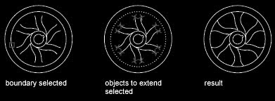
An object can be one of the cutting edges and one of the objects being trimmed. For example, in the illustrated light fixture, the circle is a cutting edge for the construction lines and is also being trimmed.
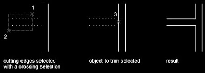
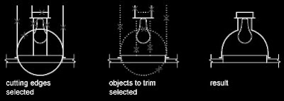
When you trim several objects, the different selection methods can help you choose the current cutting edges and objects to trim. In the following example, the cutting edges are selected using crossing selection.
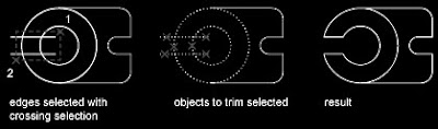
The following example uses the fence selection method to select a series of objects for trimming.
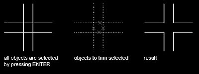
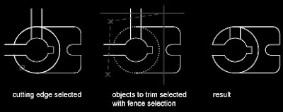
You can trim objects to their nearest intersection with other objects. Instead of selecting cutting edges, you press ENTER. Then, when you select the objects to trim, the nearest displayed objects act as cutting edges. In this example, the walls are trimmed so that they intersect smoothly.
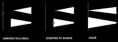
You can extend objects without leaving the TRIM command. Hold down SHIFT and select the objects to be extended.

Extend Objects
Extending operates the same way as trimming. You can extend objects so they end precisely at boundary edges defined by other objects. In this example, you extend the lines precisely to a circle, which is the boundary edge.
You can trim objects without leaving the EXTEND command. Hold down SHIFT and select the objects to be trimmed.

Trim and Extend Wide Polylines
2D wide polylines trim and extend at their centerlines. The ends of wide polylines are always square. Trimming a wide polyline at an angle causes portions of the end to extend beyond the cutting edge. If you trim or extend a tapered 2D polyline segment, the width of the extended end is corrected to continue the original taper to the new endpoint. If this correction gives the segment a negative ending width, the ending width is forced to 0.

Trim and Extend Spline-Fit Polylines
Trimming a spline-fit polyline removes the curve-fit information and changes the spline-fit segments into ordinary polyline segments. Extending a spline-fit polyline adds a new vertex to the control frame for the polyline.

Trim or Extend in 3D
You can trim or extend an object to any other object in 3D space, regardless of whether the objects are on the same plane or parallel to the cutting or boundary edges. In the TRIM and EXTEND commands, use the Project and Edge options to select one of three projections for trimming or extending:
• The XY plane of the current UCS
• The plane of the current view
• True 3D, which is not a projection

After appropriate trimming and extending (if required) your Assignment3 should look like in the picture below. Tomorrow we will cross-check what we have drafted before proceeding. Stay tuned...!

Friday, September 10, 2010

FILTER

FILTER (or 'filter for transparent use) selects, edits, and names filters for object selection.

Filter Property List
Displays a list of the filter properties that compose the current filter. The current filter is the filter that you select in Current in the Named Filters area.

Select Filter
Adds filter properties to the current filter.

Object Types and Logical Operators
Lists object types that you can filter and logical operators (AND, OR, XOR, and NOT) for grouping the filter expressions. If you use logical operators, make sure that you pair and balance them correctly in the filter list. The number of operands you can enclose depends on the operation.

For example, the following filter selects all circles except the ones with a radius greater than or equal to 1.0: Object =Circle
**Begin NOT
Circle Radius >= 1.00
**End NOT

X, Y, Z Parameters
Define additional filter parameters depending on the object. For example, if you select Line Start, you can enter the X, Y, and Z coordinate values that you want to filter.
In the filter parameters, you can use relative operators such as < (less than) or > (greater than). For example, the following filter selects all circles with center points greater than or equal to 1,1,0 and radii greater than or equal to 1:
Object = Circle
Circle Center X >= 1.0000 Y >= 1.0000 Z >= 0.0000
Circle Radius >= 1.0000

Select - Displays a dialog box listing all items of the specified type in the drawing. Select the items to filter. For example, if you select the object type Color, Select displays a list of colors to choose for the filter.

Add to List - Adds the current Select Filter property to the filter list. Filter properties that you add to the unnamed filter remain available during the current work session unless you manually delete them.

Substitute - Replaces the filter property selected in the filter property list with the one displayed in Select Filter.

Add Selected Object - Adds one selected object in the drawing to the filter list.

Edit Item - Moves the selected filter property into the Select Filter area for editing. To edit a filter property, select it and choose Edit Item. Edit the filter property and choose Substitute. The edited filter replaces the selected filter property.

Delete - Deletes a selected filter property from the current filter.

Clear List - Deletes all the listed properties from the current filter.

Named Filters - Displays, saves, and deletes filters.

Current - Displays saved filters. Select a filter list to make it current. The named filter and its list of properties are loaded from the default file, filter.nfl.
Save As - Saves a filter and its list of properties. The filter is saved in the filter.nfl file. Names can contain up to 18 characters.

Delete Current Filter List - Deletes a filter and all its properties from the default filter file.

Apply - Exits the dialog box and displays the Select Objects prompt, where you create a selection set. The current filter is used on the objects you select.

To name and save a filtered list
1. At the Command prompt, enter filter.
2. In the Object Selection Filters dialog box, under Select Filter, select a filter such as Line.
3. Click Add to List.
4. Under Save As, enter a filter name such as Line-filter.
5. Click Save As.
6. Click Apply.
The filter is applied so you can select, in this case, only lines in the drawing. If you select objects with a selection, the filter is applied to all objects in the selection area.

To use a named filter

  1. At the Select Object prompt, enter 'filter. (The apostrophe makes it a transparent command.)
  2. In the Object Selection Filters dialog box, under Select Filter, select the filter you want to use. Click Apply.
  3. Use a crossing window to specify objects for selection.
    Only the objects selected by the crossing window that match the filter criteria are selected.

Tomorrow let's get back to our Assignment3 and do some progress therein. Stay tuned...!

Thursday, September 9, 2010

QUICK SELECT 2


To create a selection set using Quick Select
In the following example, you use Quick Select to select the red objects in a drawing.
1. Click Tools menu Quick Select....At the Command prompt, enter qselect.
2. In the Quick Select dialog box, under Apply To, select Entire Drawing.
3. Under Object Type, select Multiple.
4. Under Properties, select Color.
5. Under Operator, select Equals.
6. Under Value, select Red.
7. Under How to Apply, select Include in New Selection Set.
8. Click OK.
All red objects in the drawing are selected and the Quick Select dialog box closes. Objects that are set to BYLAYER and are red because the layer color is red are not included in the selection set.

Note – If an application such as Autodesk Map was used to add a feature classification to an object, and the associated classification (XML) file is present, you can select objects by classification property. Specifically, you can select a classification in the Object Type box and a property in the Properties box.

To exclude objects from the selection set
You can exclude objects from the current selection set by using the Exclude from New Selection Set option. In the following example, you exclude all circles with a radius greater than 1 from a set of objects already selected.
1. Select several objects.
2. Click Tools menu Quick Select....At the Command prompt, enter qselect.
3. In the Quick Select dialog box, under Apply To, select Current Selection.
4. Under Object Type, select Circle.
5. Under Properties, select Radius.
6. Under Operator, select Greater Than.
7. Under Value, enter 1.
8. Under How to Apply, select Exclude from New Selection Set.
9. Click OK.
All circles with a radius greater than 1 are removed from the selection set.

To append objects to the selection set
You can use Quick Select to append objects to a current selection set. In the following example, you keep the current selection set and append all objects in the drawing that contain hyperlinks whose names begin with bld1_.

1. Click Tools menu Quick Select....At the Command prompt, enter qselect.
2. In the Quick Select dialog box, select Append to Current Selection Set.
3. In the Object Type box, select Multiple.
4. Under Properties, select Hyperlink.
5. Under Operator, select Wildcard Match.
6. Under Value, enter bld1_*.
7. Under How to Apply, select Include in New Selection Set.
8. Click OK.

Tomorrow we will explore the options of ‘Filter’ command. Stay tuned…!

Wednesday, September 8, 2010

QUICK SELECT

e. Filter / Quick Select – The last and the most important but least exploited option which is the subject matter of this article uses the filtering technique with a specified criterion to select/deselect objects.

We will go through all the TABS in the Quick Select Dialogue Box but before proceeding let’s take a look at its advantages over the conventional methods.
  1. As stated above the first advantage is user can select as well as deselect objects with this option
  2. It’s a great technique for separating and classifying clustered objects
  3. The visibility constraint is taken good care of, particularly in overlapping objects
  4. No other selection method can pick the exact object in a huge and complicated drawing
  5. In other methods user has to rely on his/her sight rather than the object properties for selection.

The list can be as big as we can stretch it. But let’s not waste more time and let’s introduce ourselves to a magical tool called Quick Select.

You can use object properties or object types to include objects in a selection set, or to exclude them.

Using either Quick Select (QSELECT) from the Properties palette or the Object Selection Filters dialog box (FILTER), you can filter selection sets by property (such as color) and by object type. For example, you can select all of the red circles in a drawing without selecting any other object, or you can select all objects except the red circles.

With Quick Select, you can quickly define a selection set based on filtering criteria that you specify, and if an Autodesk or a third-party application was used to add a feature classification to an object, you can select objects by classification property. With object selection filters, you can name and save filters for future use.

With either Quick Select or object selection filters, if you want to filter your selection set based on color, linetype, or lineweight, first consider whether these properties are set to BYLAYER for any objects in your drawing. For example, an object may appear red because its color is set to BYLAYER and the layer color is red.

Menu: Tools Quick Select...At the Command prompt, enter qselect.
Shortcut menu: End any active commands, right-click in the drawing area, and choose Quick Select.
Command entry: qselect
Specifies the filtering criteria and how you want to create the selection set from that criteria.

Apply To
Applies the filtering criteria to the entire drawing or to the current selection set (if one exists). To select a group of objects to which you want to apply the filtering criteria, use the Select Objects button. When you have finished selecting objects, press ENTER to redisplay the dialog box. ‘Apply To’ is set to Current Selection.
If ‘Append to Current Selection Set’ is selected, the filtering criteria are applied to the entire drawing.

Select Objects
Temporarily closes the Quick Select dialog box so that you can select the objects to which you want to apply the filter criteria. Press ENTER to return to the Quick Select dialog box. The ‘Apply To’ box is changed to show Current Selection. The Select Objects button is available only when you select ‘Include In New Selection Set’ and clear ‘Append to Current Selection Set’.

Object Type
Specifies the type of objects to include in the filtering criteria. If the filtering criteria are being applied to the entire drawing, the Object Type list includes all object types, including custom. Otherwise, the list includes only the object types of the selected objects.
If an application such as Autodesk Map was used to add a feature classification to an object, you can select a classification.
If you select an object type not supported by AutoCAD LT, it is greyed out in the Properties palette and is not available for changes.

Properties
Specifies the object property for the filter. This list includes all searchable properties for the selected object type. The property you select determines the options available in Operator and Value. If an application such as Autodesk® Map™ was used to add a feature classification to an object, you can select a classification property.

Operator
Controls the range of the filter. Depending on the selected property, options may include Equals, Not Equal To, Greater Than, Less Than, and *Wildcard Match. Greater Than and Less Than are not available for some properties. *Wildcard Match is available only for text fields that can be edited. For information about the available wild-card characters, see the table in Filter and Sort the List of Layers in the User's Guide.

Value

Specifies the property value for the filter. If known values for the selected property are available, Value becomes a list in which you can choose a value. Otherwise, enter a value.

How to Apply
Specifies whether you want the new selection set to include or exclude objects that match the specified filtering criteria. Select ‘Include in New Selection Set’ to create a new selection set composed only of objects that match the filtering criteria. Select ‘Exclude from New Selection Set’ to create a new selection set composed only of objects that do not match the filtering criteria.

Append to Current Selection Set
Specifies whether the selection set created by QSELECT replaces or is appended to the current selection set.

Note – QSELECT supports custom objects (objects created by another application) and their properties. If a custom object uses properties other than AutoCAD LT properties, the custom object's source application must be running in order for the properties to be available to QSELECT.

We will learn more options of QSELECT tomorrow, stay tuned...!

Tuesday, September 7, 2010

OBJECT SELECTION

Select Objects
There are three major activities an operator performs while drafting in AutoCAD
1. Drawing – Line, Arc, Polyline, Circle, Text, Dimension etc.
3. Modifying – Erase, Move, Copy, Rotate, Trim, Offset etc.

So what is the SECOND activity?
It is ‘Selecting’ which is always taken as granted and never emphasized neither in training sessions of any sort nor in practical applications. Let’s excel in the process of ‘selecting objects’ which is the highest and most common AutoCAD prompt received by almost every user around the world in a typical CAD session.

Do you know –? (TRIVIA)
  1. An average user of AutoCAD receives ‘select object’ prompt at least 275 times in an hour session
  2. An average user spends more than 35% of his/her CAD session time on selecting objects
  3. An average user hardly uses the filter and quick select tools
  4. An average user has to struggle with ‘view’ commands like ‘zoom/pan’ to get the exact selection
  5. ‘View’ commands require ‘regenerate’ and hence the productivity is decreased by 25% at the most.
So what’s the way out?
We will deal with the issue systematically by a step by step approach and let’s find where are we?
What are the selection methods?
a. Noun/Verb
b. Pick box
c. Window / Crossing
d. Fence / Wpolygon/Cpolygon
e. Filter / Quick Select


a. Noun/Verb – This is the simplest and most popular method of selection by which user specifies a ‘Letter’ i.e. alphabet to respond to ‘select objects’ prompt. As the response is in form of alphabet it is called as the Noun/Verb selection.

The Nouns/Verbs used are –
  1. All – Selects all objects in the drawing except that are on the locked/frozen layer
    This option can select any no. of objects in the drawing depending upon the layer status.
  2. L – Selects the latest object that has entered(drawn) in the drawing in chronological order
    This option will always select a SINGLE object that is the most recent one.
  3. P – Selects the object(s) that are selected for or modified by any modify command prior to the current command.

b. Pick box – This option works with both pre-command and post-command options. Which means user can select objects with a Pick box either before initiating a modification command or at the ‘select objects’ prompt of a modify command. The only difference is if the objects are to be selected before initiating the command the Pick box would be in form of cross-hair and at the ‘select objects’ prompt it would be a regular Pick box. Thus the process of selecting objects by Pick box is called as ‘picking’. Only one object can be picked (selected) at a time with this option. If the picking is done prior to initiating any command, the selected object(s) would enter the Grip Editing Mode and every object would show its respective grip points in Blue Color. When any of the blue grips is selected it turns Red and becomes HOT GRIP which means that object can be modified about that hot grip. The commands that can work with Grip Editing are move, copy, mirror, rotate and scale. But the default command associated with grips is Stretch. c. Window / Crossing – With this option a Window (from left to right) or a Crossing (from right to left) is drawn around the objects to be selected. The difference between Window and Crossing is – Window will select only the objects that are completely residing within its boundaries whereas crossing will select every object that intersects/falls within its boundaries. Therefore a crossing will always require smaller area to be covered as compared to a window as only the edges of the objects would be sufficient for selection.


d. Fence / Wpolygon / Cpolygon – With this option a fence line can be created of any shape which would intersect the objects that are to be selected. All three options will create a fence line of any no. of vertices only the difference is Fence will always be an open line while W & Cpolygon would always be a closed object. The Wpolygon is a Window Polygon i.e. anything that resides completely within this window polygon will be selected and Cpolygon is a crossing polygon i.e. anything that intersects with the edges of this polygon and resides within its boundaries will be selected.

These FOUR are the commonly used and basic methods of object selection. These options also have sub options like –
  • Select – Places selected objects in the previous selection set
  • Remove – Objects can be removed from the current selection set
  • Add – Objects can be added to the current selection set.

The last option e - Quick Select is more intricate and detailed method that needs a great deal of attention and accuracy in drafting. We will study it from tomorrow. Stay tuned...!

Monday, September 6, 2010

MANAGE PROPERTIES

CHPROP
You can change the current properties for any object in your drawing in the following ways:
  • Open the Properties (Double-click the objet) palette and view and change the settings for all properties of the object.
  • View and change the settings in the Layer control on the Layers toolbar and the Color, Linetype, Lineweight, and Plot Style controls on the Properties toolbar.

The Properties palette lists the current settings for properties of the selected object or set of objects. You can modify any property that can be changed by specifying a new value.

  • When more than one object is selected, the Properties palette displays only those properties common to all objects in the selection set.
  • When no objects are selected, the Properties palette displays only the general properties of the current layer, the name of the plot style table attached to the layer, the view properties, and information about the UCS.

You can double-click most objects to open the Properties palette when the DBLCLKEDIT command is on (the default). The exceptions are blocks and attributes, hatches, gradient fills, text, multilines, and xrefs. If you double-click any of these objects, an object-specific dialog box displays instead of the Properties palette.

Exercise – Click on the outermost left vertical line of the structure to select it. In the Layer toolbar (First to the extreme left of the Object Properties Toolbar) it will show ‘0’. Click on it to open the dropdown list and click on ‘A-Line-Sec’. This will change the layer property of the selected line from ‘0’ to ‘A-Line-Sec’.

MATCHPROP
You can copy some or all properties of one object to other objects using Match Properties. The types of properties that can be copied include, but are not limited to, color, layer, linetype, linetype scale, lineweight, plot style, and 3D thickness.

By default, all applicable properties are automatically copied from the first object you selected to the other objects. If you don't want a specific property or properties to be copied, use the Settings option to suppress the copying of that property. You can choose the Settings option at any time during the command.


Exercise – Click on the ‘Match Properties’ Button on the Standard Toolbar next to the cut, copy, paste buttons that looks like a paintbrush. Select the same line whose layer is been changed from ‘0’ to ‘A-Line-Sec’ (source objects whose properties to be copied) and then select all other lines within the structure (destination objects whose properties needs to be matched with the source).

Till this point you must have figured out one thing that you need to make quite a no. of selections for selecting the objects for modifying. Wouldn’t it be great if we can have some easier, faster and customizable object selection options? And it would also save lot of our time and effort. Isn’t it? Well, you said it. From tomorrow we will explore this important aspect of Object Selection in AutoCAD to facilitate and accelerate our drafting process. Stay tuned…!