Tuesday, October 26, 2010

CONTROL THE APPEARANCE OF DIMENSION TEXT

You can include prefixes, suffixes, and user-supplied text in dimensions. You can also control the text style and formatting used in dimension text.

The program supports a mixture of user-supplied text, prefixes and suffixes supplied by the dimension style, and generated measurements. For example, you could add a diameter symbol as a prefix to a measurement or add the abbreviation for a unit, such as mm, as a suffix. Text in this context refers to all dimension text, prefixes and suffixes, primary and alternate units, and lateral tolerances. Geometric tolerances are controlled independently.

Dimension text is treated as a single string of text, which you create and format using your text editor.

Control the Text Style in Dimensions
The appearance of dimension text is governed by the text style selected in the Dimension Style Manager, Text tab. You can choose a text style while creating a dimension style and specify a text color and a height independent of the current text style's height setting. You can also specify the gap between base dimension text and the box that surrounds it.

The text styles used for dimensions are the same text styles used by all text created in your drawing.

Supply User Text to Dimensions
In addition to the prefixes and suffixes specified for primary and alternate units, you can supply your own text as you create a dimension. Because the prefix, suffix, and user-supplied text form a single text string, you can represent tolerance stacks and apply changes to font, text size, and other characteristics using the text editor.

To add user text above and below the dimension line, use the separator symbol \X. Text that precedes this symbol is aligned with and above the dimension line. Text that follows the \X symbol is aligned with and below the dimension line. The space between the dimension line and the text is determined by the value you enter under Gap in the Annotation dialog box.

Example: User Text in Dimensions
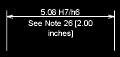
In this example, the primary dimension measurement is 5.08, and the alternate dimension measurement is 2.00. The primary units have the suffix H7/h6, and the alternate units have the suffix inches. At the text prompt, while creating the dimension, you enter the following format string:

<> H7/h6\XSee Note 26\P[ ]

The angle brackets represent the primary units, and the square brackets represent the alternate units. The \X separates text above the dimension line from text below the dimension line. The \P is a paragraph break.

The resulting text appears as follows:

Sunday, October 24, 2010

CONTROL THE LOCATION OF DIMENSION TEXT

You can locate dimension text manually and specify its alignment and orientation.
The program comes with several justification settings that facilitate compliance with international standards, or you can choose your own location for the text.

Many of the settings are interdependent. Example images in the Dimension Style Manager are updated dynamically to illustrate how text appears as you change the settings.

Align Dimension Text

Whether text is inside or outside the extension lines, you can choose whether it is aligned with the dimension line or remains horizontal. The following examples show two combinations of these options.

The default alignment is horizontal dimension text, even for vertical dimensions.

Position Dimension Text Horizontally

The position of the text along the dimension line in relation to the extension lines is referred to as text placement. To place text yourself when you create a dimension, use the Place Text Manually When Dimensioning option on the Fit tab of the Modify/New Dimension Style dialog box. Use the text placement options to automatically place text at the center of the dimension line, at either extension line, or over either extension line. 
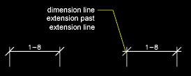
First and second extension lines are defined by the order in which you specified the extension line origins when you created the dimension. For angular dimensions, the second extension line is counterclockwise from the first. In the following illustrations, 1 is the first extension line origin and 2 the second.
If you place text manually, you can place the dimension text anywhere along the dimension line, inside or outside the extension lines, as you create the dimension. This option provides flexibility and is especially useful when space is limited. However, the Horizontal alignment options provide better accuracy and consistency between dimensions.

Position Dimension Text Vertically

The position of the text relative to the dimension line is referred to as vertical text placement. Text can be placed above or below or centered within the dimension line. In the ANSI standards, centered text usually splits the dimension line. In the ISO standards, it is usually above or outside the dimension line. For example, ISO standards permit angular dimension text to appear in any of the ways shown.Other settings, such as Text Alignment, affect the vertical alignment of text. For example, if Horizontal Alignment is selected, text inside the extension lines and centered within the dimension line is horizontal, as shown in the leftmost illustration above. The text is horizontal even if the dimension line is not itself horizontal.

Tomorrow we will explore the options to Control the Appearance of Dimension Text, stay tuned...!

Friday, October 15, 2010

CONTROL DIMENSION TEXT

You can control the placement of dimension text, arrowheads, and leader lines relative to the dimension and extension lines.
  • Fit Dimension Text Within Extension Lines
  • Control the Location of Dimension Text
  • Control the Appearance of Dimension Text

Fit Dimension Text within Extension Lines

Dimension text and arrowheads usually appear between the extension lines when there is enough space. You can specify how these elements are placed when space is limited.

Many factors, such as the size of extension line spacing and arrowhead size, influence how dimension text and arrowheads fit within the extension lines. In general, the best fit, given the available space, is applied. If possible, both text and arrowheads are accommodated between the extension lines, no matter what fit option you choose.

When creating new dimensions, you can choose to place text by entering a coordinate or using the pointing device; this is known as user-defined text placement. Alternatively, the program can compute the text position for you. The options for automatic fitting of text and arrowheads are listed in the Dimension Style Manager, Fit tab. For example, you can specify that text and arrowheads be kept together. In this case, if there is not room for both between the extension lines, they are both placed outside. You can specify that if there is room for only text or arrowheads, then either text only or arrowheads only are placed between the extension lines.

The following illustrations show how the program applies a "best fit" for arrowheads and text.


If there is no room for text between the extension lines, you can have a leader line created automatically. This is useful in cases where text outside the extension lines would interfere with other geometry, for example, in continued dimensions. Whether text is drawn to the right or the left of the leader is controlled by the horizontal justification setting on the Text tab of the Modify/New Dimension Style dialog box. Also, you can fit text and arrowheads by changing their size.

Even if the arrowheads are outside the extension lines, you can have a line drawn between the extension lines. This is called forcing an internal line and is illustrated as follows. 
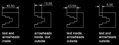
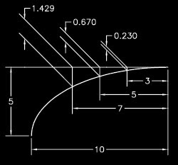
Fit Diameter Dimension Text


You can draw several different diameter dimensions depending on text placement, horizontal settings on the Text tab, and whether you select the Always Draw Dim Line Between Ext Lines options on the Fit tab.


Tomorrow we will explore the options to control the Location of Dimension Text, stay tuned...!

Thursday, October 14, 2010

CONTROL DIMENSION GEOMETRY

You can control the appearance of dimension lines, extension lines, arrowheads, and center marks.

Control Dimension Lines

You can control dimension line properties including color, lineweight, and spacing.
You can control several aspects of a dimension line. You can
  • Specify color and lineweight for visual effect and plotting
  • Suppress the dimension line or, if the dimension line is broken by text, one or both halves
  • Control the spacing between successive dimension lines in baseline dimensions
  • Control the distance by which the dimension line extends beyond the extension lines for architectural tick (oblique stroke) arrowheads
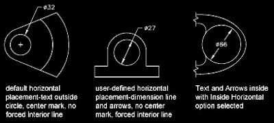
Control Extension Lines
You can control extension line properties including color, lineweight, overshoot, and offset length.
You can control several aspects of the extension lines. You can
  • Specify color and lineweight for visual effect and plotting
  • Suppress one or both extension lines if they are unnecessary, or if there is not enough space
  • Specify how far beyond the dimension line that the extension line extends (overshoot)
  • Control the extension origin offset, the distance between the extension line origin, and the start of the extension line
  • Specify a fixed length for extension lines, as measured from the dimension line toward the extension line origin
  • Specify a noncontinuous linetype, typically used for centerlines
  • Modify the angle of the extension lines of a selected dimension to make them oblique
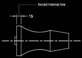
Fixed-Length Extension Lines

With the Dimension Style Manager, on the Lines tab, you can specify a dimension style that sets the total length of extension lines starting from the dimension line toward the dimension origin point. 
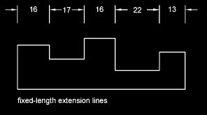
The extension-line offset distance from the origin will never be less than the value specified by the DIMEXO system variable.

Control Dimension Arrowheads

You can control the arrowhead symbols in dimensions and leaders including their type, size, and visibility.

You can choose from many standard types of arrowheads, or you can create your own arrowheads. Additionally, you can

  • Suppress the display of arrowheads, or use one arrowhead only
  • Apply a different type of arrowhead to each end of a dimension line
  • Control the size of arrowheads
  • Flip the direction of an arrowhead using the dimension shortcut menu

Note - Flipped arrowheads maintain their appearance in versions later than AutoCAD 2002. However, if you edit a drawing with flipped arrowheads in a release earlier than AutoCAD 2006, the arrowhead directions will revert to their original orientations.

Customize Arrowheads

You can create your own custom arrowheads.

Arrowheads are stored as block definitions. To use your own arrowhead, provide the name of an existing block definition. For information about creating blocks, see Create Blocks within a Drawing.

Arrowhead sizing relies on the overall dimension scale factor. When you create a dimension, the block is inserted where the arrowheads would normally go. The object's X and Y scale factors are set to arrowhead size x overall scale. The dimension line is trimmed by text gap x overall scale units at each end. To trim the dimension line, the rightmost block is inserted with a zero rotation angle for horizontal dimensioning. The leftmost block is rotated 180 degrees about its insertion point.

If you use paper-space scaling, the scale factor is computed before applying it to the arrowhead size value.

Tomorrow we will explore the tools and options to control the Dimension Text, stay tuned...!

Wednesday, October 13, 2010

COMPARE DIMSTYLES

Compare Dimension Styles and Variables

You can view all the settings in a dimension style. Dimension styles used in externally referenced drawings are differentiated from those defined in your current drawing.

You can list the dimension styles in the current drawing. You can also list all dimensioning system variables and their current status or only the variables affected by a dimension style.

When you list the current status of all dimensioning system variables, any running overrides that apply to the current dimension style are listed. You can also list the differences between a named dimension style and the current dimension style.


Use Externally Referenced Dimension Styles
The program displays externally referenced dimension style names using the same syntax as for other externally dependent named objects. When you view externally referenced dimension styles using the Dimension Style Manager, the name of the xref displays in the Styles list as Xref:drawing name with each xref style appearing below the drawing name. For example, if the drawing file baseplat.dwg has a dimension style called FRACTIONAL-1, and you attach baseplat.dwg as an xref to a new drawing, then the xref dimension style is displayed in the Styles list of the Dimension Style Manager as Xref:baseplat.dwg, and FRACTIONAL-1 appears under the drawing name.

Externally referenced dimension styles can be examined, but they cannot be modified or made current. You can use an externally referenced dimension style as a template for creating a new dimension style in your current drawing.

Format menu: Dimension Style
Dimension menu: Style
Command line: dimstyle
Compares the properties of two dimension styles or displays all properties of one style. You can print the results of the comparison to the Clipboard, and then paste to other MicrosoftWindowsapplications.


Compare Specifies the first dimension style for the comparison.
With Specifies the second dimension style for the comparison. If you set the second style to or to the same style as the first, all the properties of the dimension style are displayed.

Comparison results are displayed automatically under the following headings:
  • Description of the dimension style property
  • System variable that controls the property
  • System variable values of style properties that differ for each dimension style

Results Displays the results of the dimension style comparison. If you compare two different styles, the properties that differ are displayed. If you set the second style to or to the same style as the first, all the properties of the dimension style are displayed.

Print to Clipboard button Copies the results of the comparison to the Clipboard. You can then paste the results to other Windows applications, such as word processors and spreadsheets.

Tomorrow we will learn about controlling Dimension Elements, stay tuned…!

Monday, October 11, 2010

DIMENSION STYLE

Once you are familiar with the Text and its options, the next thing would naturally be Dimension. This is the most significant as well as intricate portion of AutoCAD for more than one reason –
1. Without Dimension the entire drawing and the geometry therein is useless.
2. Dimensions are needed to make any drawing usable as a Working Drawing.
3. If there are the most variables and settings for any AutoCAD command, it’s Dimension.
4. A single small mistake or negligence in mistake in Dimension can cost you a fortune.
5. Dimensions are the integral and phenomenal part of any Drawing Analysis.

Phew…! Are you scared of Dimensions, now? Don’t be. Whatever written above are just the facts and those need to be thoroughly understood and rightly implemented not anxiously dreaded…!?!

Alright, now today just take a look at the Overview of Dimension to start with. As for all other major elements of AutoCAD, Dimensions also do have settings called as Dimension Style.

A dimension style is a named collection of dimension settings that controls the appearance of dimensions, such as arrowhead style, text location, and lateral tolerances. You create dimension styles to specify the format of dimensions quickly, and to ensure that dimensions conform to industry or project standards.

  • When you create a dimension, it uses the settings of the current dimension style
  • If you change a setting in a dimension style, all dimensions in a drawing that use the style update automatically
  • You can create dimension sub-styles that, for specified types of dimensions, deviate from the current dimension style
  • If necessary, you can override a dimension style temporarily

You can control the appearance of dimensions by changing settings. For convenience and to help maintain dimensioning standards, you can store these settings in dimension styles.

  • Compare Dimension Styles and Variables
    You can view all the settings in a dimension style. Dimension styles used in externally referenced drawings are differentiated from those defined in your current drawing.
  • Control Dimension Geometry
    You can control the appearance of dimension lines, extension lines, arrowheads, and center marks.
  • Control Dimension Text
    You can control the placement of dimension text, arrowheads, and leader lines relative to the dimension and extension lines.
  • Control Dimension Values
    The numeric values displayed in dimensions can appear in several formats. You can also control how numeric distances are represented.

We will explore all these settings and their sub-settings before actually dimensioning our Assignment. Stay tuned…!

Saturday, October 9, 2010

TEXT

Okay, as now we are ready with our Text Style, we can proceed to putting actual Text in our Assignment. We will do this with Draw – Text command. There are two types of options for putting the text and their names suggest – Single Line Text is preferable for one liner while Multiline Text should be preferred for multiple line or paragraph text entries. Although this is very generic categorization of these types, Mtext always has advantage over single line text in terms of flexibility, efficiency and appearance as it can be easily edited, formatted and rearranged.

Use single-line text (TEXT) to create one or more lines of text, ending each line when you press ENTER. Each text line is an independent object that you can relocate, reformat, or otherwise modify.

When you create single-line text, you assign a text style and set alignment. The text style sets the default characteristics of the text object. The alignment determines what part of the text character aligns with the insertion point. Use the TEXT command to enter the text in-place, or enter -text on the command line to enter the text on the command line.

You can insert a field in single-line text. A field is text that is set up to display data that might change. When the field is updated, the latest value of the field is displayed.

The text styles used for single-line text are the same as those used for multiline text. When you create text, you assign an existing style by entering its name at the Style prompt. If you need to apply formatting to individual words and characters, use multiline text instead of single-line text.

You can also compress single-line text to fit between points that you specify. This option stretches or squeezes the text to fill the designated space.

Align Single-Line Text

As you create text, you can align it. That is, you can justify it with one of the alignment options shown in the following illustrations. Left alignment is the default. To left-align text, do not enter an option at the Justify prompt.

You can create one or more paragraphs of multiline text (mtext) in the In-Place Text Editor (or an alternative text editor) or use prompts on the command line. You can also insert text from a file saved in ASCII or RTF format.

Before entering or importing text, you specify opposite corners of a text bounding box that defines the width of the paragraphs in the multiline text object. The length of the multiline text object depends on the amount of text, not the length of the bounding box. You can use grips to move or rotate a multiline text object.

The In-Place Text Editor displays the bounding box with a ruler at the top and the Text Formatting toolbar. The editor is transparent so that, as you create text, you can see whether the text overlaps other objects. To turn off transparency while you work, check Opaque Background on the Options menu. You can also make the background of the finished multiline text object opaque and set its color.

You can set tabs and indent text to control the appearance of paragraphs in the multiline text object.

You can also insert fields in multiline text. A field is text that is set up to display data that might change. When the field is updated, the latest value of the field is displayed.

Text Style

Most characteristics of the text are controlled by the text style, which sets the default font and other options, such as line spacing, justification, and color. You can use the current text style or select a new one. The STANDARD text style is the default.

Within the multiline text object, you can override the current text style by applying formatting such as underlining, boldface, and different fonts to individual characters. You can also create stacked text, such as fractions or geometric tolerances and insert special characters, including Unicode characters, for TrueType fonts.

Note – Not all SHX and TrueType text fonts support Unicode characters.

Text Properties

In the Properties palette, you can view and change the object properties of a multiline text object, including properties that apply specifically to text:

  • Justification determines where text is inserted with respect to the bounding box and sets the direction of text flow as text is entered.
  • Line space options control the amount of space between lines of text.
  • Width defines the width of the bounding box and therefore controls where the text wraps to a new line.
  • Background inserts an opaque background so that objects under the text are masked.

Exercise – Put the text in Assignment3 as shown in the picture. Try to use both Single Line Text and Multiline Text option to have the feel of their application and behavior.

Friday, October 8, 2010

TEXT STYLE

All text in a drawing has a text style associated with it. When you enter text, the program uses the current text style, which sets the font, size, obliquing angle, orientation, and other text characteristics. If you want to create text using a different text style, you can make another text style current. The table shows the settings for the STANDARD text style.
Example: Default Text Style Settings


The settings for the current text style are displayed at the prompts on the command line. You can use or modify the current text style or create and load a new text style. Once you've created a text style, you can modify its characteristics, change its name, or delete it when you no longer need it.

Create and Modify Text Styles
Except for the default STANDARD text style, you must create any text style that you want to use.

Text style names can be up to 255 characters long. They can contain letters, numbers, and the special characters dollar sign ($), underscore (_), and hyphen (-). If you don't enter a text style name, the text styles are automatically named Stylen, where n is a number that starts at 1.

You can modify an existing text style in the Text Style dialog box by changing the settings. You can also update existing text of that text style to reflect the changes.

Certain style settings affect multiline and single-line text objects differently. For example, changing the Upside Down and Backwards options has no effect on multiline text objects. Changing Width Factor and Obliquing has no effect on single-line text.

If you rename an existing text style, any text using the old name assumes the new text style name.

You can remove unreferenced text styles from your drawing with PURGE or by deleting the text styles from the Text Styles dialog box. The STANDARD text style cannot be removed.

Change Text Style

When you change the text style of a multiline text object, the updated settings are applied to the entire object, and some formatting of individual characters might not be retained. The following table describes the effects of text style change on character formatting.

Thursday, October 7, 2010

MIRROR

As we have seen almost all the View, Format, Draw and Modify commands that are commonly required mostly used, we are all se to proceed to the non-graphical elements of AutoCAD like Text and Dimension. But before we proceed for these utilities, today let’s learn an important and interesting command under Modify. Although it belongs to the group of Modify it could as well be under the Draw menu as it actually adds additional objects into the drawing.

Mirror
You can flip objects about a specified axis to create a symmetrical mirror image. Mirroring is useful for creating symmetrical objects because you can quickly draw half the object and then mirror it instead of drawing the entire object.
You flip objects about an axis called a mirror line to create a mirror image. To specify this temporary mirror line, you enter two points. You can choose whether to erase or retain the original objects.

When you mirror text, attributes, and attribute definitions, they are reversed or turned upside down in the mirror image. If you want to prevent this, set the MIRRTEXT system variable to 0 (off). Text then has the same alignment and justification as before the mirroring.

MIRRTEXT affects text that is created with the TEXT, ATTDEF, or MTEXT commands; attribute definitions; and variable attributes. Text and constant attributes within an inserted block are mirrored as a consequence of mirroring the entire block. These objects are reversed regardless of the MIRRTEXT setting.

Mirror in 3D
With MIRROR3D, you can mirror objects across a specified mirroring plane. The mirroring plane can be one of the following:

  • The plane of a planar object
  • A plane parallel to the XY, YZ, or XZ plane of the current UCS that passes through a specified point
  • A plane defined by three specified points (2, 3, and 4)

Command line: mirror
Select objects: Use an object selection method and press ENTER to finish
Specify first point of mirror line: Specify a point
Specify second point of mirror line: Specify a point
The two specified points become the endpoints of a line about which the selected objects are mirrored. For mirroring in 3D, this line defines a mirroring plane perpendicular to the XY plane of the user coordinate system (UCS) containing the mirror line.
Erase source objects? [Yes/No] : Enter y or n, or press ENTER
Yes
Places the mirrored image into the drawing and erases the original objects. No
Places the mirrored image into the drawing and retains the original objects.

To manage the mirror properties of text objects, use the MIRRTEXT system variable. The default setting of MIRRTEXT is 1 (on), which causes a text object to be mirrored just like any other object. When MIRRTEXT is off (0), text is not reversed.

Wednesday, October 6, 2010

ROTATE – RESIZE

You can rotate objects in your drawing around a specified base point. To determine the angle of rotation, you can enter an angle value, drag using the cursor, or specify a reference angle to align to an absolute angle.

Rotate an Object by a Specified Angle
Enter a rotation angle value from 0 to 360 degrees. You can also enter values in radians, grads, or surveyor bearings. Entering a positive angle value rotates the objects counterclockwise or clockwise, depending on the Direction Control setting in the Drawing Units dialog box.

Rotate an Object by Dragging
Drag the object around the base point and specify a second point. Use Ortho mode, polar tracking, or object snaps for greater precision.

For example, you can rotate the plan view of a house by selecting the objects (1), specifying a base point (2), and specifying an angle of rotation by dragging to another point (3).

Rotate an Object to an Absolute Angle

With the Reference option, you can rotate an object to align it to an absolute angle.
For example, to rotate the part in the illustration so the diagonal edge rotates to 90 degrees, you select the objects to be rotated (1, 2), specify the base point (3), and enter the Reference option. For the reference angle, specify the two endpoints of the diagonal line (4, 5). For the new angle, enter 90.


Rotate an Object in 3D

To rotate 3D objects, you can use either ROTATE or ROTATE3D.

  • With ROTATE, you can rotate objects around a specified base point. The axis of rotation passes through the base point and is parallel to the Z-axis of the current UCS.
  • With ROTATE3D, you can specify the axis of rotation using either two points; an object; the X, Y, or Z axis; or the Z direction of the current view.

Resize
You can resize objects to make them longer or shorter in only one direction or to make them proportionally larger or smaller.

You can also stretch certain objects by moving an endpoint, vertex, or control point.

Lengthen Objects

With LENGTHEN, you can change the included angle of arcs and the length of the following objects:
• Lines
• Arcs
• Open polylines
• Elliptical arcs
• Open splines.

The results are similar to extending and trimming. You can
• Drag an object endpoint dynamically
• Specify a new length or angle as a percentage of the total length or angle
• Specify an incremental length or angle measured from an endpoint
• Specify the object's total absolute length or included angle

Stretch Objects

With STRETCH, you relocate the endpoints of objects that lie across or within a crossing selection window:
• Objects that are partially enclosed by a crossing window are stretched.
• Objects that are completely enclosed within the crossing window, or that are selected individually, are moved rather than stretched.

To stretch an object, you specify a base point and then a point of displacement.

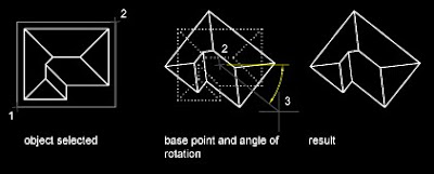
To stretch with precision, use object snaps, grid snaps, and relative coordinate entry.

Scale Objects Using a Scale Factor

With SCALE, you can make an object uniformly larger or smaller. To scale an object, you specify a base point and a scale factor. Alternatively, you can specify a length to be used as a scale factor based on the current drawing units.

A scale factor greater than 1 enlarges the object. A scale factor between 0 and 1 shrinks the object. Scaling changes the size of all dimensions of the selected object. A scale factor greater than 1 enlarges the object. A scale factor less than 1 shrinks the object.

Scale Objects Using a Reference Distance
You can also scale by reference. Scaling by reference uses an existing distance as a basis for the new size. To scale by reference, specify the current distance and then the new desired size. For example, if one side of an object is 4.8 units long and you want to expand it to 7.5 units, use 4.8 as the reference length.

You can use the Reference option to scale an entire drawing. For example, use this option when the original drawing units need to be changed. Select all objects in the drawing. Then use Reference to select two points and specify the intended distance. All the objects in the drawing are scaled accordingly.

Tuesday, October 5, 2010

ARRAY

You can create copies of objects in a rectangular or polar (circular) pattern called an array.

For rectangular arrays, you control the number of rows and columns and the distance between each. For polar arrays, you control the number of copies of the object and whether the copies are rotated. To create many regularly spaced objects, arraying is faster than copying.

Create Rectangular Arrays

A rectangular array is built along a baseline defined by the current snap rotation angle. This angle is zero by default, so the rows and columns of a rectangular array are orthogonal with respect to the X and Y axes. The default angle 0 direction setting can be changed in UNITS.

Create Polar Arrays

When you create a polar array, the array is drawn counterclockwise or clockwise, depending on whether you enter a positive or a negative value for the angle to fill.

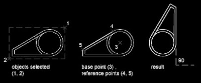
The radius of the array is determined by the distance from the specified center point to a reference or base point on the last selected object. You can use the default reference point (usually an arbitrary point that coincides with a snap point), or you can specify a new base point to be used as the reference point.

Array in 3D

With 3DARRAY, you can create a rectangular array or a polar array of objects in 3D. In addition to specifying the number of columns (X direction) and rows (Y direction), you also specify the number of levels (Z direction).

Limit the Size of Arrays

If you specify a very large number of rows and columns for an array, it may take a long time to create the copies. By default, the number of array elements that can be generated by one command is limited to 100,000. This limit is controlled by the MaxArray setting in the registry.

You can change the limit by setting the MaxArray system registry variable using (setenv “MaxArray” “n”) where n is a number between 100 and 10000000 (ten million).

Note - When changing the value of MaxArray, you must enter MaxArray with the capitalization shown.

Monday, October 4, 2010

SPLINE

A spline is a smooth curve that passes through or near a given set of points. You can control how closely the curve fits the points.
The SPLINE command creates a particular type of spline known as a nonuniform rational B-spline (NURBS) curve. A NURBS curve produces a smooth curve between control points.
You create splines by specifying points. You can close the spline so that the start and endpoints are coincident and tangent.
Tolerance describes how closely the spline fits the set of fit points you specify. The lower the tolerance, the more closely the spline fits the points. At zero tolerance, the spline passes through the points. You can change the spline-fitting tolerance while drawing the spline to see the effect.

You can use two methods for creating splines:
  • Create spline curves with the Spline option of PEDIT to smooth existing polylines created with PLINE. Such spline-fit polylines are created with uniform knot vectors and are more likely to be included in drawings created with earlier versions of the product.
  • Create splines, which are NURBS curves, with SPLINE. Drawings containing splines use less memory and disk space than those containing spline-fit polylines of similar shape.
    You can easily convert spline-fit polylines into true splines with SPLINE.

Modify SPLINE

Additional editing options are available for changing the shape of spline objects.
In addition to the general editing operations available for most objects, there are additional options available for editing splines with SPLINEDIT.

  • Fit Data. Edits the fit point data that defines the spline, including changing the tolerance.
  • Close. Changes an open spline into a continuous, closed loop.
  • Move Vertex. Moves a fit point to a new location.
  • Refine. Modifies a spline definition by adding and weighting control points and elevating the order of the spline.
  • Reverse. Changes the direction of the spline.

You also can change the tolerance of the spline. Tolerance refers to how closely the spline fits the set of fit points you specify. The lower the tolerance, the more closely the spline fits the points.

Edit Splines with Grips
When you select a spline, grips are displayed on its fit points (the GRIPS system variable must be set to 1). You can use grips to modify the shape and location of the spline.

After certain operations, fit points are discarded and grips are displayed on control points instead. These operations include trimming the spline, moving the control points, and purging the fit data. If the spline's control frame is turned on (the SPLFRAME system variable is set to 1), grips are displayed on both the spline's control points and its fit points, when available.

You can delete fit points of a spline, add fit points for greater accuracy, or move fit points to alter the shape of a spline. You can open or close a spline and edit the spline start and end tangents. Spline direction is reversible. You can change the tolerance of the spline also. Tolerance refers to how closely the spline fits the set of fit points you specify. The lower the tolerance, the more closely the spline fits the points.

Refine the Shape of a Spline

You can refine a spline by increasing the number of control points in one portion of the spline or by changing the weight of specific control points. Increasing the weight of a control point pulls the spline more towards that point. You can also refine a spline by changing its order. A spline’s order is the degree of the spline polynomial + 1. A cubic spline, for example, has order 4. The higher a spline’s order, the more control points it has.

Consider the following example. You have created a spline to represent a geographic contour. Grips are turned on, and you need to move the fourth fit point to increase accuracy. When you select the spline, grips appear at the control points. If you created the spline by fitting it through a set of points, and you haven’t purged this information using the Purge option of the SPLINEDIT command, and you select the Fit Data option, grips appear at the fit points on the selected spline instead of at the control points.

This was about the Curvilinear Objects group, tomorrow we will see some Modify commands.

Stay tuned...!

Sunday, October 3, 2010

CURVILINEAR OBJECTS

We have seen how to draw an Arc in AutoCAD. The other objects in Curvilinear Objects group are Circle, Ellipse, Donut and Spline. Today we will learn to draw Circle, Ellipse and Donut while Spline would be discovered tomorrow as it has both Drawing and Modifying options.

Let us start with Circle

You can create circles in several ways. The default method is to specify the center and the radius. Three other ways to draw a circle are shown in the illustration.
Draw a Circle Tangent to Other Objects
The tangent point is a point where an object touches another object without intersecting it. To create a circle that is tangent to other objects, select the objects and then specify the radius of the circle. In the illustrations below, the bold circle is the one being drawn, and points 1 and 2 select the objects to which it is tangent.
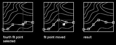
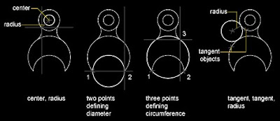
To create a circle tangent at three points, set running object snaps (OSNAP) to Tangent and use the three-point method to create the circle.

Ellipse

If you are drawing on isometric planes, use an ellipse to represent a circle viewed from an oblique angle. The easiest way to draw an ellipse with the correct shape is to use the Isocircle option of ELLIPSE. The Isocircle option is available only when the Style option of Snap mode is set to Isometric (see DSETTINGS).
Note - to represent concentric circles, draw another ellipse with the same center rather than offsetting the original ellipse. Offsetting produces an oval-shaped spline that does not represent foreshortened distances as you would expect.
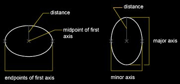
The shape of an ellipse is determined by two axes that define its length and width. The longer axis is called the major axis, and the shorter one is the minor axis.

The illustrations below show two different ellipses created by specifying axis and distance. The third point specifies only a distance and does not necessarily designate the axis endpoint.
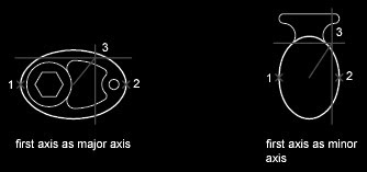
If you are drawing on isometric planes to simulate 3D, you can use ellipses to represent isometric circles viewed from an oblique angle. First you need to turn on Isometric Snap in the Drafting Settings dialog box.
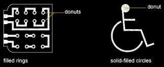
Donut
Donuts are filled rings or solid-filled circles that actually are closed polylines with width.
To create a donut, you specify its inside and outside diameters and its center. You can continue creating multiple copies with the same diameter by specifying different center points. To create solid-filled circles, specify an inside diameter of 0.
Draw menu: Donut
Command line: donut
Specify inside diameter of donut : Specify a distance or press ENTER
If you specify an inside diameter of 0, the donut is a filled circle.
Specify outside diameter of donut : Specify a distance or press ENTER
Specify center of donut or : Specify a point (1) or press ENTER to end the command
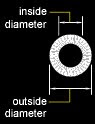
The location of the donut is set based on the center point. After you specify the diameters, you are prompted for the locations at which to draw donuts. A donut is drawn at each point specified (2). How the interior of a donut is filled depends on the current setting of the FILL command. If the Fill is ON the boundary of donut will be filled solid. If the Fill is Off the boundary of the donut will be hollow with outline.
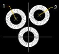
Exercise – Try to put some objects of curvilinear shapes into Assignment3 using the commands above. Those could be Furniture pieces, accessories, diagrams, paving patterns, plants and bushes, etc.

Whatever curvilinear shapes you would not be able to draw with above commands would be possible with Spline. We will explore it tomorrow, stay tuned…!

Saturday, October 2, 2010

PEDIT

To modify a polyline
1. Click Modify menu Object Polyline.
2. Select the polyline to modify.
If the selected object is a line or an arc, the following prompt is displayed:
Object selected is not a polyline.
Do you want it to turn into one? : Enter y or n, or press ENTER
If you enter y, the object is converted into a single-segment 2D polyline that you can edit. You can use this operation to join lines and arcs into a polyline. When the PEDITACCEPT system variable is set to 1, this prompt is suppressed, and the selected object is automatically converted to a polyline.
3. Edit the polyline by entering one or more of the following options:
• Enter c (Close) to create a closed polyline.
• Enter j (Join) to join contiguous lines, arcs, or polylines.
• Enter w (Width) to specify a new uniform width for the entire polyline.
• Enter e (Edit Vertex) to edit a vertex.
• Enter f (Fit) to create a series of arcs joining each pair of vertices.
• Enter s (Spline) to create an approximation of a spline.
• Enter d (Decurve) to remove extra vertices inserted by a fit or spline curve and to straighten all segments of the polyline.
• Enter L (Ltype Gen) to generate the linetype in a continuous pattern through the vertices of the polyline.
• Enter u (Undo) to reverse actions back to the start of PEDIT.
Enter x (Exit) to end the command.

Command line: PEDIT
Additional editing operations are available for changing the shape of polyline objects. You can also join separate polylines.

You can edit polylines by closing and opening them and by moving, adding, or deleting individual vertices. You can straighten the polyline between any two vertices and toggle the linetype so that a dash appears before and after each vertex. You can set a uniform width for the entire polyline or control the width of each segment. You can also create a linear approximation of a spline from a polyline.
Joined Polyline Segments
You can join a line, an arc, or another polyline to an open polyline if their ends connect or are close to each other. If the ends are not coincident but are within a distance that you can set, called the fuzz distance, the ends are joined by either trimming them, extending them, or connecting them with a new segment.
Properties of Modified Polylines
If the properties of several objects being joined into a polyline differ, the resulting polyline inherits the properties of the first object that you selected. If two lines meet a polyline in a Y shape, one of the lines is selected and joined to the polyline. Joining also causes an implicit decurve, with the program discarding the spline information of the original polyline and any polylines being joined to it. Once the joining is completed, you can fit a new spline to the resulting polyline.
Additional Editing Options for Polylines
In addition to the general editing operations available for most objects, there are additional options available for editing and joining polylines with PEDIT.
  • Close creates the closing segment of the polyline, connecting the last segment with the first. The polyline is considered open unless you close it using the Close option.
  • Join adds lines, arcs, or polylines to the end of an open polyline and removes the curve fitting from a curve-fit polyline. For an object to join the polyline, their endpoints must touch.
  • Width specifies a new uniform width for the entire polyline. Use the Width option of the Edit Vertex option to change the starting and ending widths of segments.

  • Edit Vertex marks the first vertex of the polyline by drawing an X on the screen. If you have specified a tangent direction for this vertex, an arrow is also drawn in that direction.
  • Fit creates a smooth curve consisting of arcs joining each pair of vertices. The curve passes through all vertices of the polyline and uses any tangent direction you specify.
  • Spline uses the vertices of the selected polyline as the control points, or frame, of a spline-fit polyline. The curve passes through the first and last control points unless the original polyline was closed.

  • Decurve removes extra vertices inserted by an arc-fit or spline-fit polyline and straightens all segments of the polyline.
  • Ltype Gen generates the linetype in a continuous pattern through the vertices of the polyline. When this option is turned off, the linetype is generated starting and ending with a dash at each vertex.