Control Dimension Lines
You can control dimension line properties including color, lineweight, and spacing.
You can control several aspects of a dimension line. You can
- Specify color and lineweight for visual effect and plotting
- Suppress the dimension line or, if the dimension line is broken by text, one or both halves

- Control the spacing between successive dimension lines in baseline dimensions

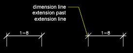
- Control the distance by which the dimension line extends beyond the extension lines for architectural tick (oblique stroke) arrowheads
 Control Extension Lines
 You can control several aspects of the extension lines. You can
- Specify color and lineweight for visual effect and plotting
- Suppress one or both extension lines if they are unnecessary, or if there is not enough space

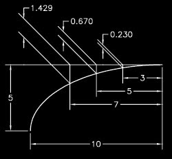
- Specify how far beyond the dimension line that the extension line extends (overshoot)

- Control the extension origin offset, the distance between the extension line origin, and the start of the extension line

- Specify a fixed length for extension lines, as measured from the dimension line toward the extension line origin

- Specify a noncontinuous linetype, typically used for centerlines

- Modify the angle of the extension lines of a selected dimension to make them oblique
 Fixed-Length Extension Lines
 With the Dimension Style Manager, on the Lines tab, you can specify a dimension style that sets the total length of extension lines starting from the dimension line toward the dimension origin point.
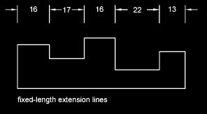 The extension-line offset distance from the origin will never be less than the value specified by the DIMEXO system variable.
Control Dimension Arrowheads
You can control the arrowhead symbols in dimensions and leaders including their type, size, and visibility.
You can choose from many standard types of arrowheads, or you can create your own arrowheads. Additionally, you can
- Suppress the display of arrowheads, or use one arrowhead only
- Apply a different type of arrowhead to each end of a dimension line
- Control the size of arrowheads
- Flip the direction of an arrowhead using the dimension shortcut menu
Note - Flipped arrowheads maintain their appearance in versions later than AutoCAD 2002. However, if you edit a drawing with flipped arrowheads in a release earlier than AutoCAD 2006, the arrowhead directions will revert to their original orientations.
Customize Arrowheads
You can create your own custom arrowheads.
Arrowheads are stored as block definitions. To use your own arrowhead, provide the name of an existing block definition. For information about creating blocks, see Create Blocks within a Drawing.
Arrowhead sizing relies on the overall dimension scale factor. When you create a dimension, the block is inserted where the arrowheads would normally go. The object's X and Y scale factors are set to arrowhead size x overall scale. The dimension line is trimmed by text gap x overall scale units at each end. To trim the dimension line, the rightmost block is inserted with a zero rotation angle for horizontal dimensioning. The leftmost block is rotated 180 degrees about its insertion point.
If you use paper-space scaling, the scale factor is computed before applying it to the arrowhead size value.
Tomorrow we will explore the tools and options to control the Dimension Text, stay tuned...!
No comments:
Post a Comment