Although it is not mandatory, it is good idea to set limits of our assignment in view of use of GRID and structure of drawing. It helps a great way to work within limits, especially in the initial times of practice. That way we can better understand the concepts of Coordinates and Composition. Secondly limits would come handy in case you need to plot your drawing from Model Space itself, not recommended though!
Setting the limits higher than our maximum spread of drawing is always advisable for having enough space to facilitate the arrangement and composing of the drawing elements.
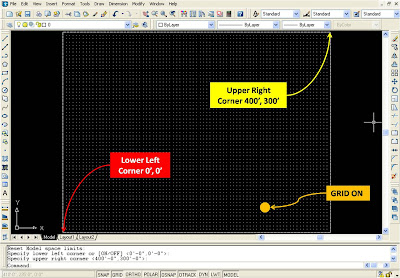
For our assignment we will set the limits to 400’, 300’ so that we have enough space for all our 5 elements. To do this click on Format – Drawing Limits.
This will return a prompt
Specify lower left corner or [ON/OFF]
Specify lower left corner or [ON/OFF] <0'-0",0'-0">:
Specify upper right corner <1'-0",0'-9">: 400',300' press enter
On turns on limits checking. When limits checking is on, you cannot enter points outside the grid limits. Because limits checking tests only points that you enter, portions of objects such as circles can extend outside the grid limits.
Note – LIMCHECK System Variable controls the creation of objects outside the grid limits. When set to ‘0’ objects can be created outside the limits and when set to ‘1’ objects cannot be created outside the limits.
Set the GRID and SNAP spacing to 5’ and turn them on. Draw a Rectangle from 0,0 to 400’,300’ and click View – Zoom – All. Your screen should look like one in the picture. Save your drawing in D drive – Exercises folder – Chapter1 subfolder with the name Assignment3.dwg.
The last setting in this group of three under Format menu is Thickness.
Thickness is a property of certain objects that gives them a 3D appearance.
The 3D thickness of an object is the distance of that object extended, thickened, above or below its location in space. Positive thickness extrudes upward in the positive Z direction; negative thickness extrudes downward (negative Z). Zero (0) thickness means that there is no 3D thickening of the object. The Z direction is determined by the orientation of the UCS at the time the object was created. Objects with a non-zero thickness can be shaded and can hide other objects behind them.

The thickness property changes the appearance of the following types of objects:
- 2D solids
- Arcs
- Circles
- Lines
- Polylines (including spline-fit polylines, rectangles, polygons, boundaries, and donuts)
- Text (only if created as a single-line text object using an SHX font)
- Traces
- Points
Modifying the thickness property of other types of objects does not affect their appearance. You can set the default thickness property for new objects you create by setting the THICKNESS system variable. Change the thickness property of an existing object using the Properties palette. The 3D thickening is applied uniformly on an object: a single object cannot have different thicknesses for its various points.
You may need to change the 3D viewpoint to see the effect of thickness on an object.
Tomorrow we will learn the fundamental and significant concept of AutoCAD – Layer.
Meanwhile practice with limits and thickness. Stay tuned..!
No comments:
Post a Comment